The relative motion between the two links or machine elements are completely constrained in a defined direction, Then the pair is known as the Kinematic Pair. Let’s discuss the Kinematic pairs in more details with the different constraints and, definitions of links and the machine elements.
First of all, from the above definition, a pair is the combination of the kinematic links or machine elements.
What is a Kinematic link or machine element?
In a machine, each part which moves relative to some part is known as the kinematic link or an element.
Each link or an element may be a single body or comprised of multiple bodies fastened together. So the bodies do not move relative to one another.
These bodies fastened together to make kinematic links are called the structures.
This link or an element must be a resistant body and should have a relative motion then it is said as the kinematic link or a machine element.
In order to be a kinematic link, The link should not be a rigid link.
Kinematic links types
There are three different types of links to transmit the motion.
- Rigid Link: There is no deformation occurs during transmitting the motion. In reality, they don’t exist. But in solving mathematical models we need to consider the rigid links.
- Flexible Link: A partial deformation will occur during transmitting the motion. They do not affect the transmission of motion.
- Fluid Link: Fluid as the transmission medium for the motion. For example in the case of Hydraulic presses, Jacks and brakes.
We have discussed what is the link, now we have to understand the constraints to make the kinematic pair.
Types of Constrained motions
1. Completely Constrained
When motion between the two kinematic links or Machine elements are limited to a definite direction. then the pair is completely constrained.
For example, the piston and the cylinder. The piston is completely constrained which it can only move in a defined direction.
2. Incompletely constrained
When the motion between the pair can be more than in one direction then it is said as the incomplete constraint.
For example, The above square block in the slot can be moved in two directions.(Translation along the X direction, Y direction) So this can be an example for the Incomplete constraint.
3. Successfully constrained
When the motion between the elements forming the pair and the constrained motion is completed by other means, then the motion said as the successfully constrained.
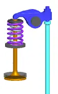
The motion of the valve is kept in the position by a pre-compressed. These are the examples for the successfully constrained motions. Piston reciprocated in the cylinder is also said as the example for the successfully constrained motions.
What is Overconstrained?
When two elements are joined and making a kinematic pair, which means there is one degree of freedom is free in a defined direction. then the this is said as the kinematic pair to make the relative motion. If we add one more constraint to the pair against the relative motion then that is called as the overconstrained.
Usually, we used to hear this expression when we used the CAD software during the mating of two components in the assembly. Which means that you are defining more number of constraints than the required. But in reality, Overconstrained can not be done.
Classification of Kinematic Pairs
Kinematic pairs are classified with different consideration. Those are according to the type of relative motion between them, type of contact between them and the type of closure.
Following are the Kinematic pairs according to the type of relative motion between them
Sliding Pair
When two elements of a pair are connected in such a way that one element can only slide relative to the other. Such type of Kinematic pair is known as a sliding pair.
Examples of Sliding pair
- Piston and cylinder
- tailstock on the lathe machine
- ram and its guides in its shaper
Turning Pair
When two elements of a pair are connected in such a way that one element can only turn or revolute about a fixed axis of another link or element is known as the turning pair.
Examples of Turning pair
- crankshaft fitted in the casing with the journal bearing
- Cycle wheel
- Lathe machine spindle
Rolling Pair
When two elements of a pair are connected in such a way that one element can only rollover a fixed link or element is known as the Rolling pair.
Examples of Rolling pair: rollers in roller Bearings
Screw Pair
When two elements of a pair are connected in such a way that one element can turn about the other element by screw threads, the pair is known as the Screw pair.
Examples of Screw pair: Bolt and nut
Spherical Pair
When two elements of a pair are connected in such a way that one element should be in spherical shape turns or swivels about the other fixed element, the pair is known as the spherical pair.
Examples of Spherical pair: Ball and socket joint
These are all the different types of Kinematic pairs according to the type of relative motion between them. Now we will discuss the Kinematic pairs according to the type of contact between them.
Lower Pair
When two elements of a pair have a surface contact when relative motions take place, the surface of one element slides over the surface of the other element. The pair are known as the Lower Pair
Sliding pair, turning pair and screw pairs come under the lower pairs
Higher Pair
When the two elements of a pair have a line or point contact when relative motion takes place, the motion between the two elements is partly turning and partly sliding, then the pair is known as higher pair.
Friction discs, the toothed gears and belt and rope drives, Cam and followers, roller bearing come under the higher pairs.
These are all the different types of Kinematic pairs according to the type of contact between them. Now we will discuss the Kinematic pairs according to the type of closure.
Self Closed pair
When the two elements of a pair are connected together mechanically in such a way that only required kind of relative motion occurs, it is then known as self closed pair.
The lower pairs are self closure pairs
Force Closed pair
When the two elements of a pair are not connected mechanically but are kept in contact by the action of external forces, the pair is said to be a force-closed pair.
The cam and follower is an example of force closed pair, as it is kept in contact by the forces exerted by spring and gravity.
These are the different types of Kinematic pairs.
Conclusion
We have discussed what is a link or a machine element, how do we constrain them (Types of constraints), what is meant by a kinematic pair, and what are the different kinematic pairs available. If you have any further thoughts on this topic, let us know in the comment section below.
Leave a Reply