Drafting with Creo 6.0 is very interesting and fun and when you need to show or Draw Centre Marks in Creo Drawings is easy. But with some features like revolving, and extrude cuts, the centerlines can not be called on to the drawings easily. Figuring out this can be pretty frustrating as it should not be since Creo is one the best CAD software for engineers who work with large assemblies and also a wide variety of families of products with different sizes and types. In order to show or Draw Centre Marks for the revolve feature in Creo Drawings is a myth for some people. Let us not too worry about this and solve this with ease.
For people new to Creo, PTC Creo is a family or suite of CAD software, that supports product design for discrete manufacturers and is developed by PTC.

Showing Centre Marks in Creo
For extruded features:
- You can set the configuration option show_axes_for_extr_arcs to yes, and then the axis will be automatically added when creating new Extruded features, for example for all fillets in Sketch.
- If you prefer to only have an axis for individual items and arcs you can instead use Geometry Points in the Sketch to specify where the axis will be added.
- Datum Axis can also be created afterwards from the Model tab of the Creo ribbon picking the extruded cylindrical surface.
- All those Model datums can then be shown from Annotate > Show Model Annotations dialogue in the drawing.
For revolved features:
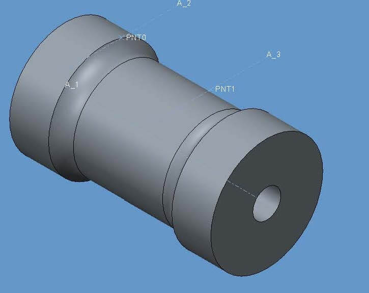
- The above solutions are not available and an additional Sketch can be used to insert Datum Points and then create Datum Axis, anticipating their location in drawing views

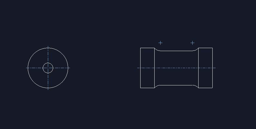
Then Show Model Annotations dialogue can be used to display centre marks in 2D:

Other 2D methods in Creo Drawing
- Directly sketch entities in the drawing and modify their line style to mimic centerlines.
Do you think we have covered all the possible ways to Show or Draw Centre Marks in Creo? Let us know in the comment section below.
Source: PTC community, cgorni

Leave a Reply