As you know, there are 3 different types of cotter joints. The Sleeve and Cotter Joint is one of them. The other two are the Socket and Spigot Cotter Joint, and Gib and cotter joint. In this article, we are going to discuss this Sleeve and Cotter joint construction and how to design this Cotter Joint to avoid possible failures in different parts of this cotter joint.
Cotter Joint
A Cotter joint is a joint which is locked by a cotter. A cotter is a flat wedge-shaped piece of rectangular cross-section and its width is tapered from one end to another for an easy adjustment. Mostly it is tapered on one side but sometimes it may be tapered on both sides.
- A Typical Cotter has a taper that varies from 1 in 48 to 1 in 24 and it may be increased up to 1 in 8, if a locking device is provided.
- In order to lock the cotter in place we need additional locking device such as a taper pin or a set screw on the lower end of the cotter to keep in its place.
- The cotter is usually made of mild steel or wrought iron.
- The cotter joint comes under the temporary fastening method.
- Cotter Joints are used to connect rigidly two co-axial rods or bars which are subjected to axial tensile or compressive forces.
- This cotter joints can be fount in well know applications such as in
- Connecting a piston rod to the cross-head of a reciprocating steam engine,
- Connecting a piston rod and its extension as a tail or pump rod,
- in strap end of connecting rod
Sleeve and Cotter Joint
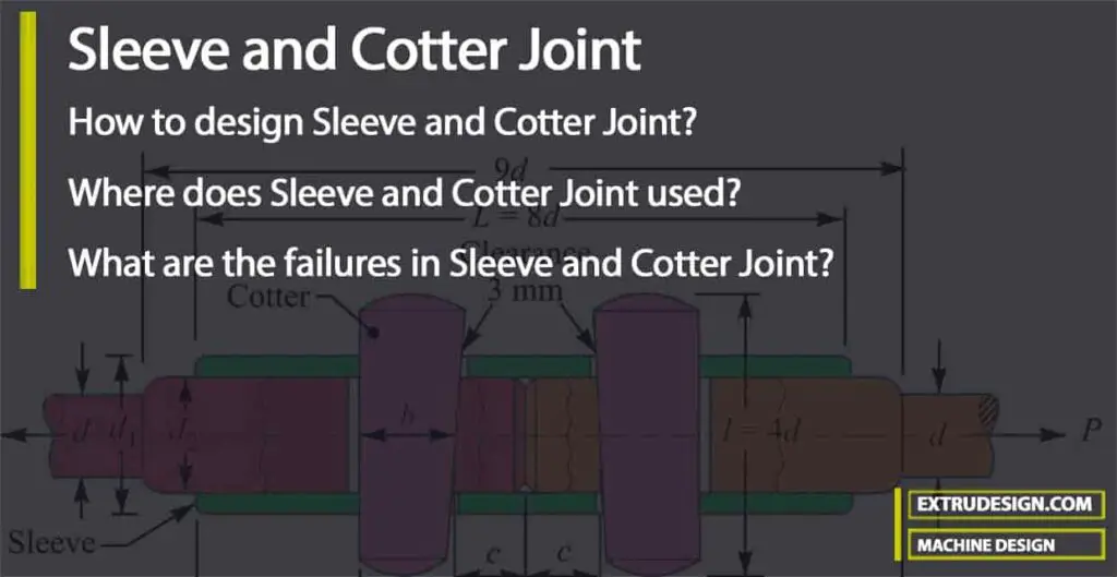
Following is the Sleeve and Cotter Joint schematic diagram.

As we have seen above, the sleeve and cotter joint is used to connect two round rods or bars.
- In this type of joint, a sleeve also called as muff is used over the two rods and then two cotters (one on each rod end) are inserted in the holes provided for them in the sleeve and rods.
- The Sleeve and cotter is usually have a taper of 1 in 24. It may be noted that the taper sides of the two cotters should face each other as shown in above schematic diagram.
- The clearance is so adjusted that when the cotters are driven in, the two rods come closer to each other thus making the joint tight.
Design of Sleeve and Cotter Joint
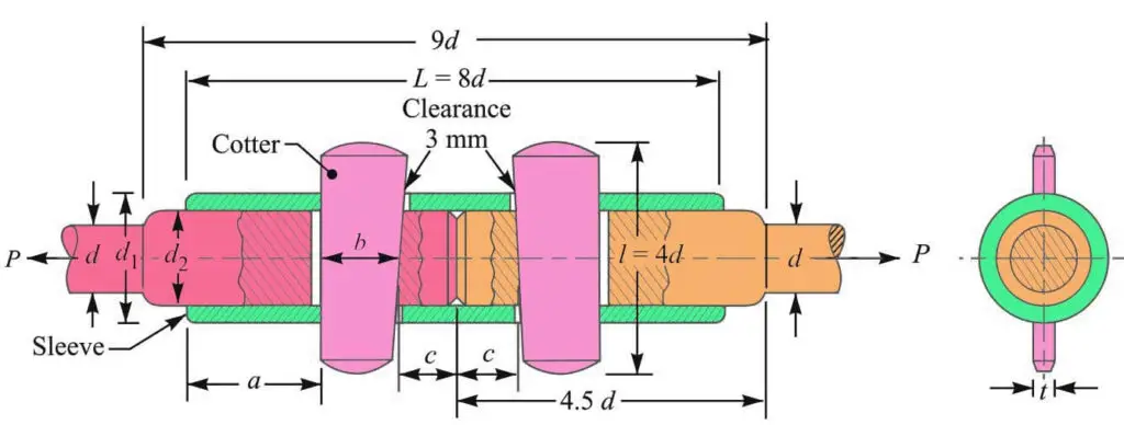
Let us assume
P = Load carried by the rods,
d = Diameter of the rods,
d1 = Outside diameter of sleeve,
d2 = Diameter of the enlarged end of the rod.
t = Thickness of cotter,
l = Length of cotter,
b = Width of cotter,
a = Distance of the rod end from the beginning to the cotter hole (inside the sleeve ends as mentioned above),
c = Distance of the rod end from its end to the cotter hole,
σt= Permissible tensile stress for the material of the rods and cotter
τ = Permissible shear stress for the material of the rods and cotter
σc = Permissible crushing stress for the material of the rods and cotter
Standard dimensions of Sleeve and Cotter Joint
The various proportions of the dimensions for the sleeve and cotter joint in terms of the diameter of the rod (d) are prescribed as follows.
Outside diameter of sleeve d1 = 2.5d
Diameter of enlarged end of rod d2 = Inside diameter of sleeve = 1.25 d
Length of sleeve L = 8 d
The thickness of cotter t = d2/4 or 0.31 d
Width of cotter b = 1.25 d
Length of cotter l = 4 d
Distance of the rod end (a) from the beginning to the cotter hole (inside the sleeve end) = Distance of the rod end (c) from its end to the cotter hole = 1.25d
In order to determine these dimensions for a sleeve and cotter joint, we need to consider the possible failures that may occur in the different parts of this joint and the permissible stress for the materials used for this cotter joint. These possible failures are mentioned below.
- Failure of the rods in tension
- Failure of the rod in tension across the weakest section
- Failure of the rod or cotter in crushing
- Failure of sleeve in tension across the slot
- Failure of cotter in shear
- Failure of rod end in shear
- Failure of sleeve end in shear
These possible failures of different parts of the Sleeve and cotter joint are considered to determine the above parameters.
1. Diamter of the Rods
By considering the Failure of the rods in tension we can determine the diameter of the rods that need to be connected with the sleeve and cotter joint.
The rods may fail in tension due to the tensile load P. We know that
We know that the cross-sectional Area resisting tearing inside the rod is given by
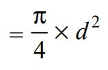
∴ The Tearing strength of the rods will be the product of the permissible tensile stress (σt) and the cross-sectional area that resist the tearing. We can write the relation as follows

Now in order to resist the load, we must Equate this tearing strength to load (P), We can write

From this above relation, we can determine the required diameter of the rods (d).
2. Diameter Of The Enlarged End Of The Rod (d2)
By considering the Failure of the rod in tension across the weakest section, we can determine the diameter of the enlarged end of the rod as shown in the above diagram.
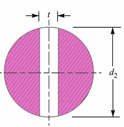
Since the weakest section is that section of the rod that has a slot in it for the cotter, therefore The cross-sectional Area resisting tearing of the rod across the slot is given by

and tearing strength of the rod across the slot will be the product of the permissible tensile stress (σt) in and the cross-sectional area that resists this stress. We can write the relation as follows

Now in order to resist the load, we must be Equating this tearing strength to load (P), We can write

From this equation, we can determine the diameter of the enlarged end of the rod (d2) may be obtained.
Also, the thickness of the cotter is usually taken as d2/4.
3. Induced crushing stress (σc) in rods or cotter
By considering the Failure of the rod or cotter in crushing, we can determine the Induced crushing stress in the rod or cotter.
We know that the cross-sectional area that resists crushing of a rod or cotter to avoid failure, is given by
= d2 × t
The Crushing strength will be the product of the area that resists the crushing and the permissible crushing stress.
We can write the relation as = d2 × t × σc
In order to resist the load, we must equate this crushing strength to the applied load (P), we can write have
P = d2 × t × σc
From this relation, the induced crushing stress in the rods or the cotter can be determined.
4. Outside Diameter Of The Sleeve (d1)
By considering the Failure of the sleeve in tension across the slot, we can determine the outside diameter of the sleeve.
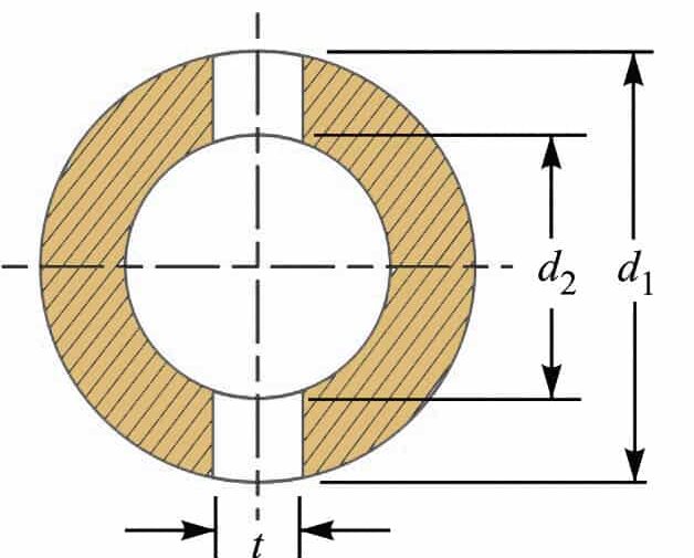
We already knew that the cross-sectional area that resists tensile stress in the sleeve across the slot to avoid failure is given by

∴ Tearing strength of the sleeve across the slot
∴ The Tearing strength of the sleeve across the slot is will be the product of the permissible tensile stress (σt) and the cross-sectional area of the sleeve across the slot. We can write the relation as follows

Now in order to resist the load, we must Equate this tearing strength to load (P), We can write

From this relation, we can determine the outside diameter of the sleeve (d1).
5. Width Of Cotter (b)
The most important part of the Cotter’s joint is the cotter. We need to prevent any chance of failure in the cotter.
By considering the Failure of the cotter in shear, we can determine the width of the cotter.
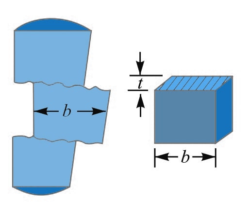
As you can see the above schematic representation of the Cotter being pulled away by the two equal opposite loads results in double shear.
The shearing area of the cotter will
= 2 b × t
and shearing strength of the cotter will be the product of the permissible shear stress of the
= 2 b × t × τ
Now equate this relation to the load (P), we can write as
P = 2 b × t × τ
From this relation, we can determine the width of cotter (b).
6. Distance of the rod end from the beginning to the cotter hole (a)
By considering the Failure of the rod end in shear, we can determine the distance of the rod end from the beginning to the cotter hole.
Since the rod end is in double shear, therefore the area resisting the shear of the rod end
= 2 a × d2
and shear strength of the rod end will be equal to the product of the area resisting the shear and the permissible shear stress. We can write this as follows
= 2 a × d2 × τ
Now let us equate this relation to the load (P), we can write
P = 2 a × d2 × τ
From this relation, we can determine the distance of the rod end from the beginning to the cotter hole (a).
7. Distance of the rod end from its end to the cotter hole (c)
By considering the Failure of sleeve end in shear, we can determine the distance of the rod end from its end to the cotter hole.
Since the sleeve, the end is in double shear, therefore the area resisting shear of the sleeve end is written as follows
= 2 (d1 – d2) c
and shear strength of the sleeve end is = 2 (d1 – d2 ) c × τ
Let us equate this relation to the load (P), we can write
P = 2 (d1 – d2) c × τ
From this relation, we can determine the distance (c).
These are all the required parameters that we need to determine for the Sleeve and the Cotter Joint.
Let us solve a sample problem to design a Sleeve and Cotter Joint.
Example Problem Statement
Design a sleeve and cotter joint to resist a tensile load of 60 kN. All parts of the joint are made of the same material with the following allowable stresses :
Permissible tensile Stress σt= 60 MPa = 60 N/mm2
Permissible Shear Stress τ = 70 MPa = 70 N/mm2
Permissible Crushing Stress σc= 125 MPa = 125 N/mm2
Answer:
Given load Load P = 360 kN = 60 × 103 N
1. Diameter of the rods
Let d = Diameter of the rods., Considering the failure of the rods in tension. We know that load (P),

60 × 103 = (π/4) × d2 × 60
d 2 = 60 × 103 / 47.13
d 2 = 1273
d = 35.7
We got the diameter of the rod as 35.7, we can assume the rod diameter d as 36mm.
2. Diameter of enlarged end of rod and thickness of cotter
Let d2 = Diameter of enlarged end of the rod, and
t = Thickness of cotter. It may be taken as d2 / 4.
Considering the failure of the rod in tension across the weakest section (i.e. slot). We know that load (P),

60 × 103 = [(π/4) × (d2)2 – d2 × (d2 / 4)] × 60
(d2)2 = 60 × 103 / 32.13
(d2)2 = 1867
d2 = 43.2
The Diameter of the enlarged end of the rod and thickness of the cotter is 43.2mm, we can assume it as 44mm.
and thickness of cotter will be t = d2 / 4 = 44/4 = 11mm.
Let us now check the induced crushing stress in the rod or cotter. We know that load (P),
P = d2 × t × σc
60 × 103 = d2 × t × σc
60 × 103 = 44 × 11 × σc
60 × 103 = 484 σc
σc = 60 × 103 / 484
σc = 124 N/mm2
We have the crushing stress of 124N/mm2, which is within the given permissible crushing stress value of 125 N/mm2, therefore the dimensions d2 and t are within safe limits.
3. Outside diameter of sleeve
Let d1 = Outside diameter of sleeve.
Considering the failure of the sleeve in tension across the slot. We know that load (P)

60 × 103 = {(π/4) × [(d1)2 -(44)2]- (d1-44) × (11)} × 60
60 × 103 = {0.7854 (d1) 2 – 1520.7 – 11 d1 + 484} × 60
(d1)2 – 14 d1 – 2593 = 0
Solving this second-order algebraic equation we get d1 = 58.4mm. let us take the outside diameter of the sleeve as 60mm.
4. Width of cotter
Let b = Width of cotter.
Considering the failure of cotter in shear. Since the cotter is in double shear, therefore load (P),
P = 2 b × t × τ
60 × 103 = 2 b × t × τ
60 × 103 = 2 × b × 11 × 70
60 × 103 = 1540 b
b = 60 × 103 / 1540
b = 38.96
We got the width of the cotter as 38.96mm, let us take the width of the cotter as 40mm.
5. Distance of the rod from the beginning to the cotter hole (a)
Let a = Required distance.
Considering the failure of the rod end in shear. Since the rod end is in double shear, therefore load (P),
P = 2 a × d2 × τ
60 × 103 = 2 a × d2 × τ
60 × 103 = 2 a × 44 × 70
60 × 103 = 6160 a
a = 60 × 103 / 6160
a = 9.74
We got the distance of the rod from the beginning to the cotter hole (a) is 9.74mm, let us take this value as 10mm.
6. Distance of the rod end from its end to the cotter hole
Let c = Required distance.
Considering the failure of the sleeve end in shear. Since the sleeve end is in double shear, therefore load (P),
P = 2 (d1 – d2) c × τ
60 × 103 = 2 (d1 – d2) c × τ
60 × 103 = 2 (60 – 44) c × 70
60 × 103 = 2240 c
c = 60 × 103 / 2240
c = 26.78
we got the distance of the rod end from its end to the cotter hole (c) is 26.78, let us take this value as 28mm.
These are all parameters of the sleeve and Cotter Joint.
Applications of Cotter Joints
- Historically, the Cottar joint has been used to connect connecting rods to steam engines and pumps used in dumping mines.
- Cotter Joints are used between the piston rod and the tail of the pump rod.
- Cotter’s joints are used between the slide spindle and the fork of the valve mechanism.
- Cotter and Dowell arrange to join two parts of a flywheel.
- Foundation bolt: mainly used for fastening foundation and construction heavy machines
- In an automobile engine, the cotter joint is used to connect the extension of the piston rod with the connecting rod in the crosshead.
- The Cottar joint has historically been used to connect connecting rods to steam engines and pumps of dumping mines.
- It is used in bicycles to connect the paddle to the sprocket wheel.
- Use a wet air pump to join a tail rod with the piston rod.
- It is used to connects two rods of equal diameter subjected to axial forces.

Leave a Reply