Topic: Design of a Cotter Foundation bolt
A foundation bolt is used to fasten a structure or a machine to a permanent base. Following is an example of an ordinary Foundation Bolt used for the structure to hold on the ground.

Cotter Foundation Bolt
Cotter Foundation Bolt is a combination of a Cotter with the Foundation bolt in order to provide a much more convenient way of fastening. So in this article, we will see how to design a cotter Foundation bolt.
In many of the applications such as fastening heavy machinery to foundations, Cotter Foundation bolts are used in conjunction with foundation and holding down bolts.
Construction and Design of Cotter Foundation Bolt
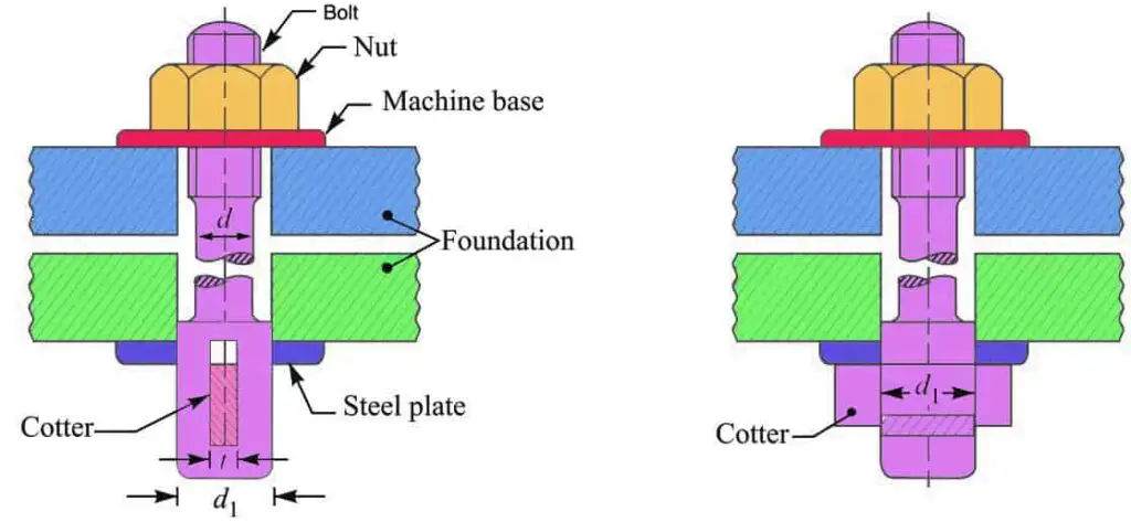
As you can see from the below, the schematic representation of the Foundation bolt with cotter.
- The foundation bolt is dropped down from above and the cotter is driven in from the side.
- Now, this Bolt assembly is tightened by screwing down the nut, then the cotter is tightly held in place.
- It is importaint to use two base plates in the Cotter Foundation bolt as shown in the figure.
- one base plate is under the nut and the other under the cotter are used.
- These two base plates provide more bearing area in order to take up the tightening load on the bolt as well as to distribute the same uniformly over the large surface.

Let assume that
d = Diameter of the bolt,
d1 = Diameter of the enlarged end of the bolt,
t = Thickness of cotter, and
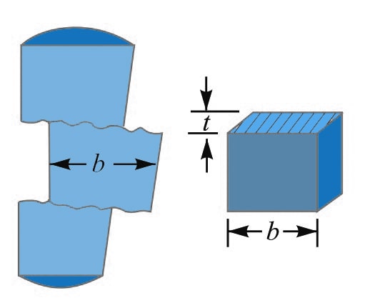
b = Width of cotter.
In designing a cotter foundation bolt, the following modes of failure may occur. Or at least we need to consider these failures in order to determine the design parameters of the Cotter Foundation Bolt.
The various modes of failure of the cotter foundation bolt are
- Failure of bolt in tension
- Failure of the enlarged end of the bolt in tension at the cotter
- Failure of cotter in shear
- Failure of cotter in crushing
1. Diameter of the Bolt (d)
To determine the diameter of the bolt, we need to assume the Failure of the bolt under tension.
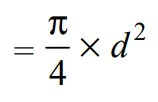
We know that the cross-sectional Area resisting tearing inside the bolt is given by

The Tearing strength of the bolt will be the product of the induced tensile stress (σt) and the cross-sectional area that resist the tearing inside the bolt.
We can write the relation as follows

Now in order to resist the load, we must Equate this tearing strength to load (P), We can write

From this relation, we can determine the diameter of bolt (d).
2. Diameter Of The Enlarged End Of The Bolt (d1)
To determine the diameter of the enlarged end of the bolt, we need to assume there is Failure of the enlarged end of the bolt under tension at the cotter.
We know that area resisting tearing in the bolt enlarged end is

The tearing strength of the enlarged end of the bolt will be the product of the induced tensile stress (σt) and the cross-sectional area that resist the tearing inside the enlarged end of the bolt.

Now in order to resist the load, we must Equate this tearing strength to load (P), We can write

From this relation, we can determine the diameter of the enlarged end of the bolt (d1).
The thickness of the cotter is usually taken as d1 / 4.
3. width of cotter (b)
To obtain the width of the cotter, we need to consider the Failure of the cotter in double shear.

Since we assumed that the cotter is in double shear, therefore area resisting shearing
= 2 b × t
The Shearing strength of the cotter will be the product of induced/permissible shear stress and the area resisting shearing
= 2 b × t × τ
Equating this to the load (P), we have
P = 2 b × t × τ
From this relation, the width of cotter (b) can be determined.
4. Induced Crushing Stress In The Cotter (σc)
Failure of cotter in crushing can lead us to determine the induced crushing stress in the cotter.
We know that area resisting crushing in cotter is
= b × t
The Crushing strength of the cotter will be the product of crushing stress and the area resisting crushing in the cotter
= b × t × σc
Equating this to the load (P), we have
P = b × t × σc
From this equation, the induced crushing stress in the cotter may be checked.
These are all the parameters required to design the Cotter Foundation bolt.
Let us solve a sample problem to design a cotter foundation bolt.
Example Problem Statement
Design and draw a cottered foundation bolt that is subjected to a maximum pull of 50 kN. The allowable stresses are given as σt= 80 MPa ; τ = 50 MPa ; and σc = 100 MPa.
Answer:
Given data:
Pulling load (P) = 50 kN = 50 × 103 N
Permissible tensile stress (σt) = 80 MPa = 80 N/mm2
Permissible Shear stress (τ) = 50 MPa = 50 N/mm2
Permissible Crushing stress (σc) = 100 MPa = 100 N/mm2
1. Diameter of bolt
Let us say d = Diameter of the bolt.
Considering the failure of the bolt in tension. We know that load (P)

50 × 103 = π /4 ×d2 ×σt
50 × 103 = π /4 ×d2×80
50 × 103 = 62.84 d2
d2 = 50 × 103 / 62.84
d2 = 795.7
d = 28.2
The diameter of the bolt we obtained from above is 28.2mm, let us take this value as 30mm.
2. Diameter of enlarged end of the bolt and thickness of cotter
Let us say
d1 = Diameter of enlarged end of the bolt, and
t = Thickness of cotter. It will be taken as d1 / 4.
Considering the failure of the enlarged end of the bolt in tension at the cotter. We know that load (P),

50 × 103 = [ (π /4)(d1)2 – d1 × (d1 / 4)] × 80
50 × 103 = 42.84 (d1)2
(d1)2 = 50 × 103 / 42.84
(d1) 2= 1167
d1 = 34
The diameter of the enlarged end of the bolt is 34mm, let us take this value as 36mm to be on the safe side of the design.
The thickness of the cotter (t) = d1 / 4 = 36/4 = 9 mm.
3. Width of cotter
Let b = Width of cotter.
Considering the failure of cotter in shear. Since the cotter is in double shear, therefore load (P),
P = 2 b × t × τ
50 × 103 = 2 b × t × τ
50 × 103= 2 b × 9 × 50
50 × 103= 900 b
b = 50 × 103 / 900
b = 55.5
We got the width of the cotter value as 55.5mm, let us take this value as 60mm.
Let us now check the crushing stress induced in the cotter. Considering the failure of cotter in crushing.
We know that load (P),
P = b × t × σc
50 × 103 = b × t × σc
50 × 103= 60 × 9 × σc
50 × 103= 540 σc
σc = 50 × 103 / 540
σc= 92.5 N/mm2
Since the induced crushing stress of 92.5 N/mm2 is less than the permissible value of 100 N/mm2, therefore the design of the cotter foundation bolt with the above-calculated parameters is safe.
This is how you can calculate the design parameters of a cotter foundation bolt.

Leave a Reply