The hydraulic machines, which convert the hydraulic energy into mechanical energy, are called turbines while the hydraulic machines which convert mechanical energy into hydraulic energy are called pumps. Hydraulic energy is in the form of pressure energy. If the mechanical energy is converted into pressure energy by means of centrifugal force acting on the fluid, the hydraulic machine is called a centrifugal pump. In the previous article, we discussed the details of the Centrifugal Pump such as its construction, its main parts, how the Centrifugal Pump works and the Multistage Centrifugal Pumps. Let us discuss the work done by the Centrifugal Pump

Centrifugal Pump
As we mentioned Centrifugal Pump converts the mechanical energy into pressure energy by means of centrifugal force acting on the fluid.
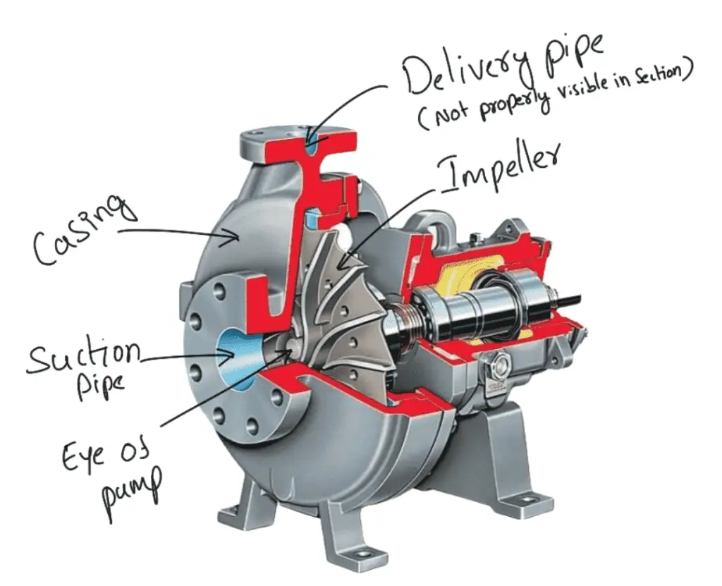
- The centrifugal pump acts as a reverse of an inward radial flow reaction turbine.
- This means that the flow in centrifugal pumps is in the radial outward directions.
- The centrifugal pump works on the principle of forced vortex flow.
- This means that when a certain mass of liquid is rotated by an external torque, the rise in pressure head of the rotating liquid takes place.
- The rise in pressure head at any point of the rotating liquid is proportional to the square of the tangential velocity of the liquid at that point.
- Thus at the outlet of the impeller, where the radius is more, the rise in pressure head will be more and the liquid will be discharged at the outlet with a high-pressure head.
- Due to this high-pressure head, the liquid can be lifted to a high level.
Work Done by the Centrifugal Pump
In the case of the centrifugal pump, work is done by the impeller on the water. The expression for the work done by the impeller on the water is obtained by drawing velocity triangles at the inlet and outlet of the impeller in the same way as for a turbine.
The water enters the impeller radially at the inlet for the best efficiency of the pump, which means the absolute velocity of water at the inlet makes an angle of 90° with the direction of motion of the impeller at the inlet.
Hence angle α = 90° and Vw1 = 0
For drawing the velocity triangles, the same notations are used for turbines. The following figure shows the velocity triangles at the inlet and outlet tips of the vanes fixed to an impeller.
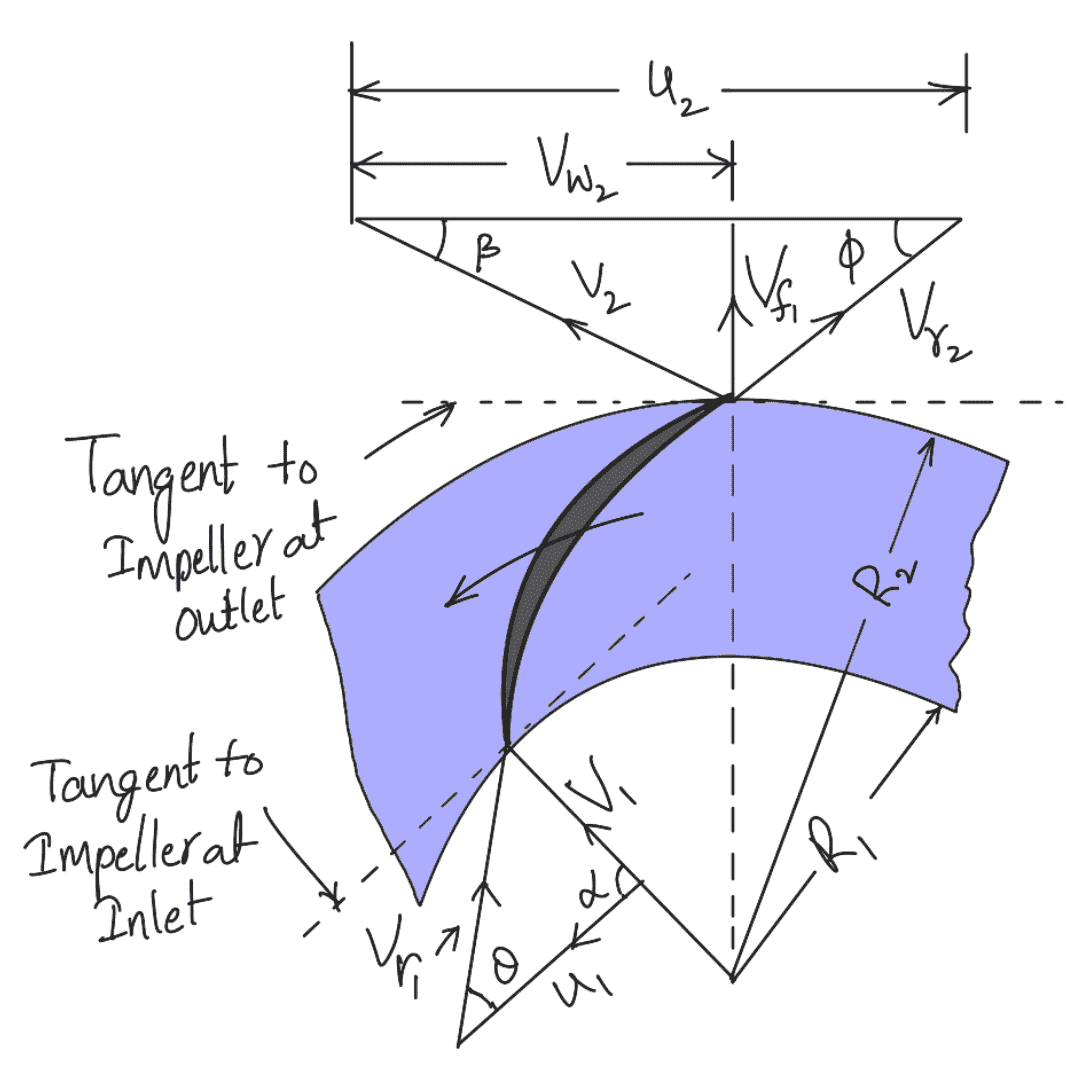
Let
N = Speed of the impeller in r.p.m.
D1 = Diameter of the impeller at the inlet
u1 =Tangential velocity of the impeller at the inlet
D2 = Diameter of the impeller at the outlet,
u2 = Tangential velocity of the impeller at the outlet
V1 = Absolute velocity of water at the inlet
Vr1 = Relative velocity of water at the inlet
α = Angle made by absolute velocity (V1) at the inlet with the direction of motion of the vane
θ = Angle made by relative velocity (Vr1) at the inlet with the direction of motion of the vane
V2, Vr2 ß and φ are the corresponding values at the outlet
As the water enters the impeller radially which means the absolute velocity of water at the inlet is in the
radial direction and hence angle α = 90° and Vw1 = 0.
A centrifugal pump is the reverse of a radially inward flow reaction turbine. But in the case of a radially inward flow reaction turbine, the work done by the water on the runner per second per unit weight of the water striking per second is given by equation as
W = 1/g [Vw1 u1 – Vw2 u2]
Work done by the impeller on the water per second per unit weight of water striking per second
Work done by the impeller = – [Work done in case of turbine]
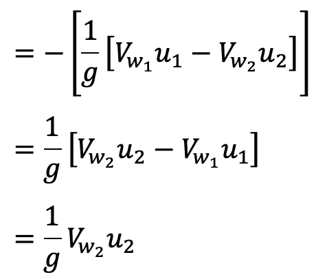
Work done by impeller on water per second

where W = Weight of water = ρ × g × Q
where Q = Volume of water
and
Q = Area × Velocity of flow
Q = πD1B1 × Vf1
Q = πD2B2 × Vf2
where B1 and B2 are the widths of the impeller at the inlet and outlet and Vf1 and Vf2 are the velocities of flow at the inlet and outlet.
Equation (a) gives the head imparted to the water by the impeller or energy given by the impeller to water per unit weight per second.
Let us solve an example problem to understand how to calculate Work Done By The Centrifugal Pump.
Example Problems on Work Done by Centrifugal Pump
Problem Statement: The internal and external diameters of the impeller of a centrifugal pump are 200mm and 400 mm respectively. The pump is running at 1200 r.p.m. The vane angles of the impeller at the inlet and outlet are 20° and 30° respectively. The water enters the impeller radially and the velocity of flow is constant. Determine the work done by the impeller per unit weight of water.
Answer:
Given data in the problem statement are
Internal diameter of impeller, D1 = 200mm = 0.20m
External diameter of impeller, D2 = 400mm = 0.40m
Speed, N = 1200 RPM
Vane angle at the inlet, θ = 20°
Vane angle at outlet, φ = 30°
Water enters radially means, α = 90° and Vw1 = 0
(Generally, if this condition is not mentioned in the given problem statement, then the water is assumed to be entering radially unless stated otherwise)
The Velocity of flow, Vf1 = Vf2
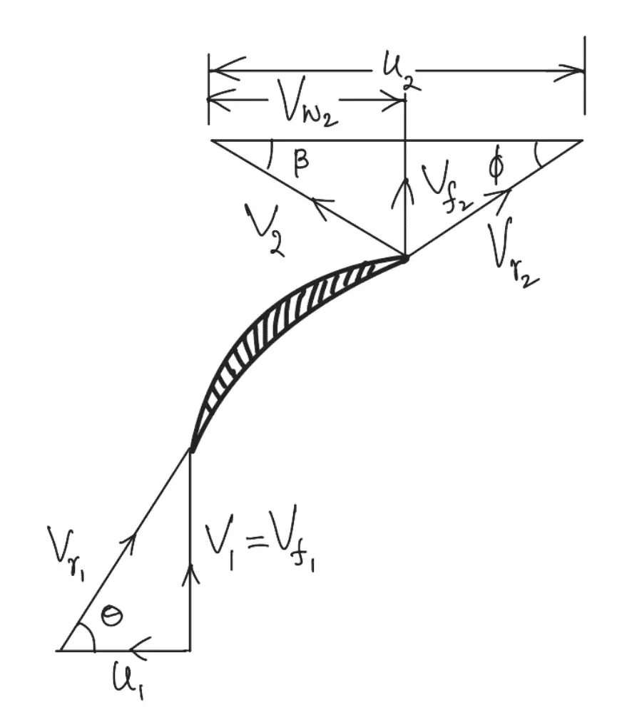
The Tangential velocity of the impeller at the inlet and outlet are

From the inlet velocity triangle,

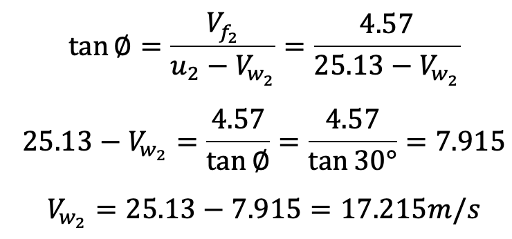
From the outlet velocity triangle,
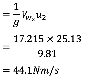
The work done by the impeller per kg of water per second is given by equation (a)
This is how you can calculate the Work Done by the Centrifugal Pump. Let us know what you think about this article in the comment section below.

Leave a Reply