In Fluid mechanics, we have discussed Power Transmission Through Pipes in the previous article. We also discussed energy losses of fluid flow through pipes and studied the Viscous fluid flow in the pipe. In this article, let us see how to calculate the Power Transmission Through Nozzles and the maximum efficiency conditions for the flow of fluid through nozzles.

Flow Through Nozzles
A Nozzle is a device designed to control the direction or characteristics of a fluid flow. Especially Nozzles are used to increase the velocity of the fluid flow as it exits an enclosed chamber or pipe.
Following are some of the Nozzle applications
- Generally, Nozzles are used in steam turbines, gas turbines, water turbines and jet engines, and Jet propulsions.
- Nozzles are used for flow measurement e.g. in venturi meter.
- Nozzles are also used to remove air from a condenser.
- Injectors for pumping feed water to boilers.
The following is a schematic representing a nozzle fitted at the end of a long pipe.
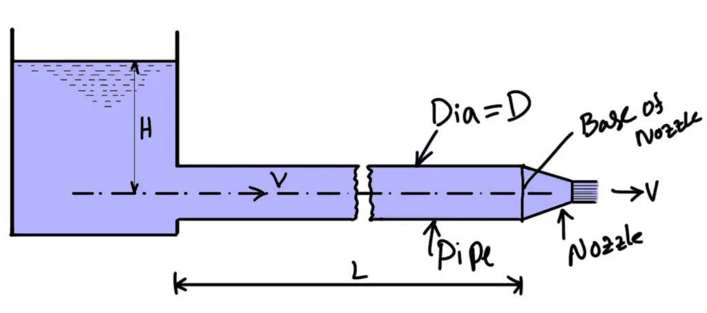
The total energy at the end of the pipe consists of pressure energy and kinetic energy. By fitting the nozzle at the end of the pipe, the total energy is converted into kinetic energy.
Thus nozzles are used, where higher velocities of flow are required. The examples are
- In the case of the Pelton turbine, the nozzle is fitted at the end of the pipe (called penstock) to increase velocity.
- In case of extinguishing the fire, a nozzle is fitted at the end of the hose pipe to increase velocity.
Let
D = diameter of the pipe,
L = length of the pipe,
A = area of the pipe
V = velocity of flow in the pipe,
H = total head at the inlet of the pipe,
d = diameter of the nozzle at the outlet,
v = velocity of flow at the outlet of nozzle,
a = area of the nozzle at the outlet
f = co-efficient of friction for the pipe
Loss of head due to friction in pipe,
Head available at the end of the pipe or at the base of nozzle = Head at the inlet of pipe – head lost due to friction
Neglecting minor losses and also assuming losses in the nozzle are negligible, we have
Total head at the inlet of pipe = total head (energy) at the outlet of nozzle + losses
But total head at the outlet of nozzle = kinetic head
From continuity equation in the pipe and outlet of nozzle,
Substituting this value in the above equation, we get
Discharge through nozzle = a × v
Power Transmitted Through Nozzle
The kinetic energy of the jet at the outlet of the nozzle will be
Now the mass of liquid at the outlet of nozzle per second = ρav
The kinetic energy of the jet at the outlet per sec
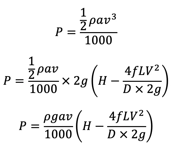
Power in kW at the outlet of the nozzle
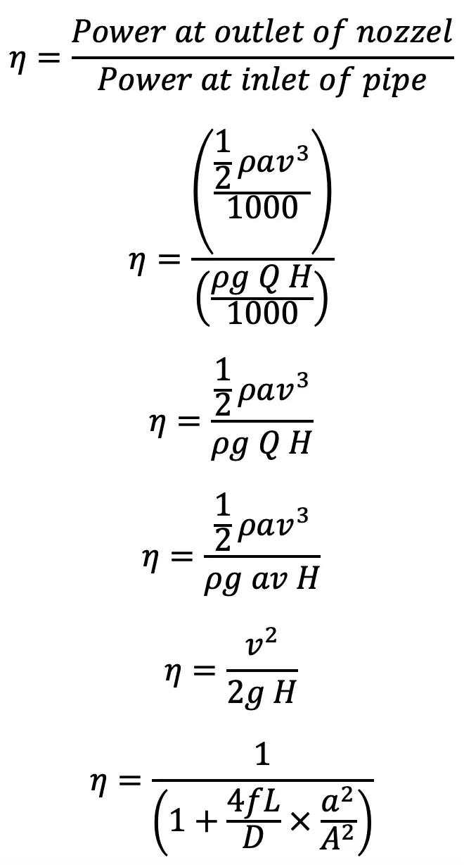
The efficiency of power transmission through the nozzle
Condition for Maximum Power Transmitted Through Nozzle
We know that, the total head at the inlet of pipe = total head at the outlet of the nozzle + losses
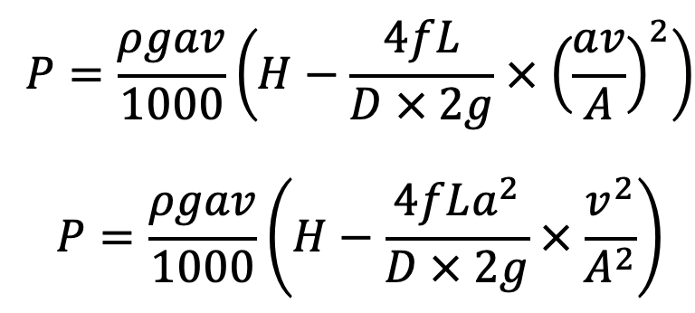
But power transmitted through the nozzle
Now from the continuity equation
Substituting the value of V in equation (c), we get The Power transmitted through the nozzle
The power (P) will be maximum, when d(P)/dv = 0
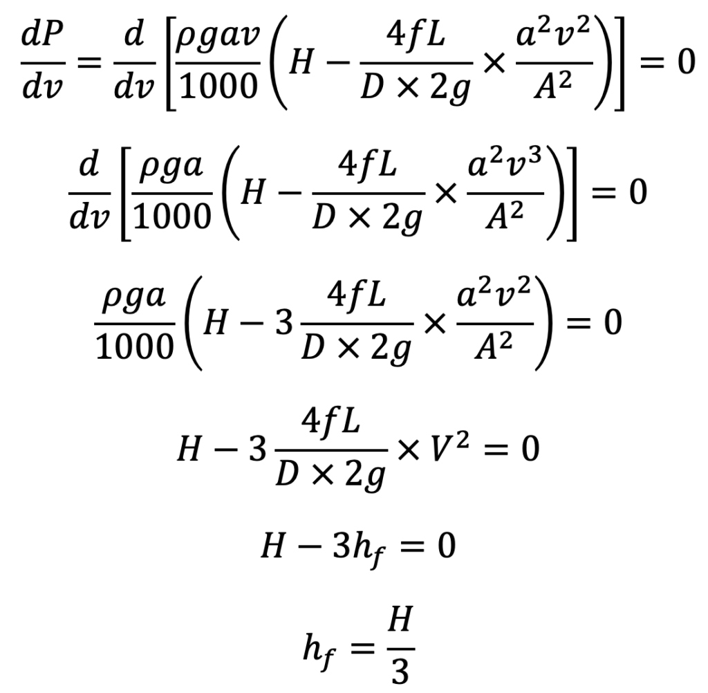
Equation (d) gives the condition for maximum power transmitted through the nozzle. It states that power transmitted through the nozzle is maximum when the head loss due to friction in the pipe is one-third of the total head supplied at the inlet of the pipe.
Diameter of Nozzle for Maximum Transmission of Power Through Nozzle
For maximum transmission of power, the condition is given by equation (d) as
But we know
But H is also = total head at the outlet of nozzle + losses
Equating the two values of H, we get
But from the continuity equation
Substituting this value of V in the above equation, we get
Further,
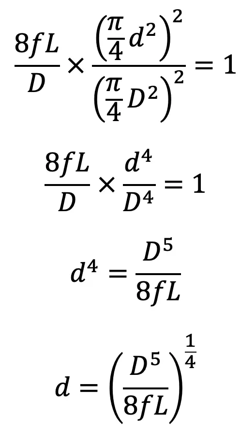
Equation (f) helps us to determine the Diameter of the Nozzle for the Maximum Transmission of Power Through the Nozzle.
From Equation (e)
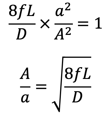
Equation (g) gives the ratio of the area of the supply pipe to the area of the nozzle and hence from this equation, the diameter of the nozzle can be obtained.
This is all about the Power Transmission Through Nozzles.
Leave a Reply