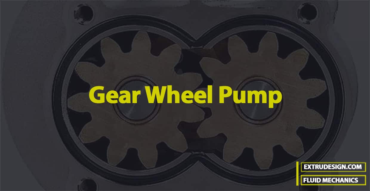
The gear wheel pump is a rotary pump in which two gears mesh to provide the pumping action. This type of pump is mostly used for cooling water and pressure oil to be supplied for lubrication to motors, turbines, machine tools etc.

Fluid Systems
A fluid system is defined as a device in which power is transmitted with the help of a fluid which may be liquid (water or oil) or a gas (air) under pressure. Most of these devices are based on the principles of fluid statics and fluid kinematics. Following are the different devices that come under the Fluid systems.
- The hydraulic press
- The hydraulic accumulator
- The hydraulic intensifier
- The hydraulic Ram
- The hydraulic Lift
- The hydraulic Crane
- The fluid or hydraulic coupling
- The fluid or hydraulic torque converter
- The Air Lift pump
- The gear-wheel pump
Gear-Wheel Pump
The gear pump is a rotary pump in which two gears mesh to provide the pumping action. This type of pump is mostly used for cooling water and pressure oil to be supplied for lubrication to motors, turbines, machine tools etc. Although the gear pump is rotating machinery, its action on the liquid to be pumped is not dynamic and it merely displaces the liquid from one side to the other. The flow of liquid to be pumped is continuous and uniform.

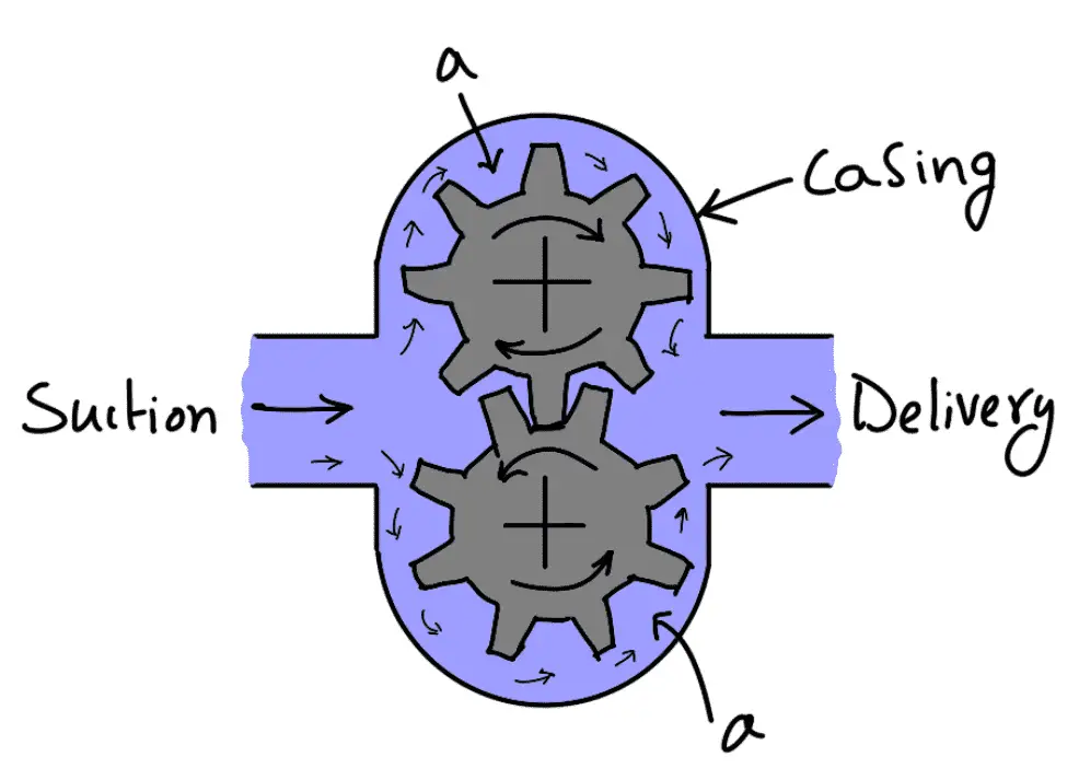
The above figure shows the gear pump, which consists of two identical intermeshing gears working in a fine clearance inside a casing. One of the gears is keyed to a driving shaft. The other gear revolves due to the driving gear. The space between the teeth and the casing is filled with oil. The oil is carried around between the gears from the suction pipe to the delivery pipe.

The mechanical contact between the gears does not allow the flow from the inlet to the outlet directly. The outer radial tips of the gears and sides of the gears form a part of moving oil.
The oil pushed into the delivery pipe, cannot back into the suction pipe due to the meshing of the gears. The theoretical oil pumped per second is obtained as:
Let
N = Speed of rotating gear in r.p.m.,
a = Area enclosed between two successive teeth and casing,
n = Total number of teeth in each gear,
L = Axial length of teeth
Volume of oil discharged per revolution = 2 × a × L × N m3
Discharge/second = Volume of oil per revolution × No. of revolution in one second

The actual discharge will be less than the theoretical discharge.
Now,

This is the volumetric efficiency of the Gear Wheel Pump. From this, we can calculate the volumetric efficiency of the Gear Wheel Pump.
Advantages of gear Wheel pumps
- They are self-priming, meaning they can create a vacuum to draw fluid into the pump without external assistance.
- They give constant delivery for a given speed, meaning they can provide a smooth and pulseless flow of fluid.
- They are compact and light in weight, meaning they are easy to transport and install.
- They can handle a wide range of viscosities, meaning they can pump fluids with different thicknesses and properties.
- They have high efficiency, meaning they can convert mechanical energy into fluid energy with minimal losses.
Disadvantages of gear Wheel pumps
- They have high wear and tear, meaning they require frequent maintenance and replacement of parts.
- They have a limited pressure range, meaning they cannot operate at very high or very low pressures.
- They have high noise levels, meaning they can cause disturbance and discomfort to the surroundings.
- They cannot handle abrasive or corrosive fluids, meaning they can get damaged or clogged by particles or chemicals in the fluid.
This is all about Gear Wheel Pumps. Let us know what you think about this article in the comment section below.

Leave a Reply