Casting is a manufacturing process used in foundries to produce metal components from Ferrous and Non-ferrous metals. Casting is one of the most important manufacturing processes among all processes. Casting is pouring molten metal into the moulds. Let us discuss How a Mould is prepared for Casting Process in step by step process and also the important properties of the sand used for the Mould preparation.

Moulding Sand
Mould making is the process of manufacturing by shaping liquid raw material using a rigid frame called a mould. Moulding sand will be used for manufacturing the mould. Consists of 3 basic elements
- Silica sand particles
- Clay
- Water or sodium silicate
In foundries, sand is used for making moulds. We can obtain Natural sand on the bed and banks of rivers provides an abundant source, although high-quality silica sand is also mined.

Sand is chemically SiO2 – silicon dioxide in granular form.
Ordinary river sand contains a percentage of clay, moisture, non-metallic impurities and traces of magnesium and calcium salts besides silica grains. This sand, after suitable treatment, is used for mould making.
Moulding Sand Properties
Preparing a mould for a casting process starts with selecting the suitable sand. Good, well-prepared moulding sand should have the following properties:
- Refractoriness: it should be able to withstand high temperatures.
- Permeability: the ability to allow gases, water vapour and air to pass through it.
- Greensand strength: when a mould is made with moist sand, it should have sufficient strength, otherwise, the mould will break.
- Good flowability: when it is packed around a pattern in a moulding box, it should be able to fill all nooks and corners, otherwise, the impression of the pattern in the mould would not be sharp and clear.
- Good collapsibility: it should collapse easily after the casting has cooled down and has been extracted after breaking the mould. It is particularly important in the case of core making.
- Cohesiveness: the ability of sand grains to stick together. Without cohesiveness, the moulds will lack strength.
- Adhesiveness: the ability of sand to stick to other bodies. If the moulding sand does not stick to the walls of the moulding box, the whole mould will slip through the box.
Properties like permeability, cohesiveness and green strength are dependent upon the size and shape
of sand grains, as also as the binding material and moisture content present in the sand.
Clay is a natural binder. Chemical binders like bentonite are sometimes added if clay content in natural sand is not enough.
Standard tests have been devised by foundrymen to determine the properties of sand. Generally, fresh moulding sand prepared in the foundry will be having the following composition.
| Element | Composition in % | |
| Silica | 75% (approx.) | |
| Clay | 10–15% | |
| Bentonite | 2–5% (as required) | |
| Coal dust | 5–10% | |
| Moisture | 6–8% |
Core sand (Sand used to Prepare the Core) has to have the oil as the main binding material. Because when the core gets surrounded by molten metal it causes the oil to vaporise. This increases the collapsibility of sand and makes it easy to remove sand from the holes in the casting.
Mould Making Step by step
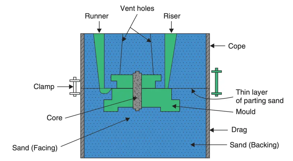
A complete mould ready for pouring is shown in the following figure.

Mould making is a very skilled operation. We shall describe, step by step, the procedure for making a
mould for a split pattern.
- Place the bottom half of the split pattern on a flat moulding board, with the parting surface facing downwards. Sprinkle some parting sand on the pattern and the moulding board. Parting sand is silica sand without any clay or binding material. Then place a moulding box to enclose the pattern.
- Spread facing sand to cover all parts of the pattern up to a depth of 20–25 mm. Facing sand is freshly prepared moulding sand. Fill up the remaining space left in the moulding box with backing sand. Backing sand is prepared by reconditioning the previously used foundry sand which is always available on the foundry floor. The use of backing sand reduces the requirement of facing sand, which is quite costly.
- Next, the sand in the moulding box is rammed with a special tool. Ramming means pressing the sand down by giving it gentle blows. Sand should be packed in the moulding box tightly but not too tightly. If as a result of ramming, the level of sand goes down in the box, more sand should be filled in and rammed. Then with a trowel, level the sand lying on the top of the mould box. Next, take a venting tool (it is a long thick needle), and make venting holes in the sand taking care that they are not so deep as to touch the pattern. This moulding box will form the lower box, and is called “drag”.
- Now turn over the moulding box gently and let it rest on some loose sand after levelling the foundry floor. Place the top half of the split pattern in the correct relative position on the flat surface of the bottom half of the pattern. Place another empty moulding box on the top of the first moulding box (i.e., drag) and clamp them temporarily. Sprinkle some parting sand upon the exposed surface of the top half of the pattern and the surrounding sand. Cover the pattern in 20–25 mm deep facing sand. Place two taper pins at suitable places, where the runner and riser are to be located. Full up the box with backing sand, pack in the sand with a ramming tool, level sand and make venting holes. Remove taper pins and make room on the foundry floor, next to the drag box, for keeping the “cope” as the top box is called Unclamp the moulding boxes, lift ‘cope’ and place it down on its back. Now the flat parting surface of both parts of the split pattern can be seen one in each box.
- In order to lift the patterns from cope and the drag, locate the tapped holes on the flat surface and screw in a lifting rod in these holes. This provides a handle with which the patterns can be easily lifted up vertically. However first the patterns are loosened a bit by rapping these handles gently before lifting them. This minimises the damage to sand moulds.
- After removing wooden pattern halves, the mould cavities may be repaired in case any corners etc., have been damaged. This is a delicate operation. Also, if any sand has fallen into the mould cavity, it is carefully lifted or blown away by a stream of air.
- In case, any cores are used to make holes in the casting, this is time for placing the cores in the mould cavity. Of course, the cores are supported properly by means of core prints or other devices like chaplets etc. Lack of adequate support for cores may result in their displacement from the correct position when the liquid metal is poured in.
- Before closing the mould boxes, graphite powder is sprinkled on the mould surface in both boxes. In the drag box, a gate is cut below the location of the runner (in the coping box). The molten metal poured into the runner will flow through the gate into the mould cavity. In case, the moulds have been dried, instead of graphite powder, a mould wash containing a suspension of graphite in water is lightly spread over the mould surface. After all these operations are complete, the coping box is again placed on the drag and clamped securely. Now the mould is ready for pouring molten metal. Molten metal is poured until it shows up in the riser. It ensures that mould cavities are full of metal and that they will not run short.
Sand moulds are of three kinds:
(a) Greensand mould: In such moulds, pouring of molten metal is done, when the sand is still moist.
(b) Skin dry moulds: Such moulds are superficially dried by moving a flame over the mould cavity so that mould dries only up to a depth of a few mm.
(c) Dry moulds: After preparing such moulds, they are dried by keeping the mould for 24–36 hours in an oven whose temperature is maintained at 130–150°C. Dry sand moulds are stronger and cannot give rise to any moisture-related defects in the casting. Mould wash improves the surface finish of castings.
Gates, Runners and Risers
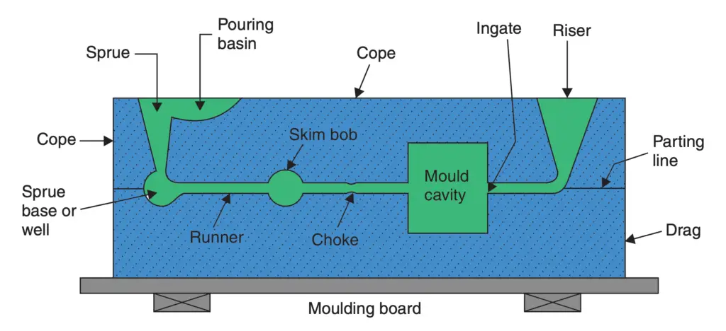
The passage provided in the mould through which molten metal will flow into the mould cavity is known as the gating system. It is provided by scooping out the sand in the drag box to cut necessary channels.
The various terms associated with the gating system will be clear by studying the gating system shown in the following figure.

- The top of the runner hole in the cope is widened into a pouring basin.
- The molten metal then flows down through the runner into a well from where it enters the gating system and into the mould cavity.
- At a suitable location in the mould cavity, the riser hole is connected. Without a gate, the metal would have fallen straight into the mould cavity damaging it.
- Besides, the gating system is so designed as to trap impurities from entering the mould cavity.
- The function of the riser is twofold.
- Firstly, it provides a visible indicator that the mould cavity is full.
- Secondly and more importantly, the molten metal in the riser provides a reservoir to feed the shrinkage caused as the casting progressively solidifies and cools.
- It is desirable that the metal in the riser remains molten as long as possible. This is done by providing a ‘‘hot-top”.
Sometimes, the riser does not open out to the top surface of the coping box, it is then called a blind riser. In that case, its sole function is to feed the shrinkage associated with the solidification of molten metal.
Conclusion
We have discussed How a Mould is prepared for Casting Process in step by step process and also the important properties of the sand used for the Mould preparation. Also discussed is the gating system for the mould cavity. Let us know what you think about this article in the comment section below.

Leave a Reply