In the previous articles we have discussed calculating shaft diameter if it is subjected to twisting moment, bending moment, fluctuating, and Axial Load. Following are the list of all the article we have discussed.
How to calculate the shaft diameter from the torque?
How to calculate Shaft Diameter under Twisting, Bending Moment, and Fluctuating?
How to calculate Shaft Diameter under Axial Load?
Let us solve the example problem of calculating Shaft diameter for a pinion gear.
Problem Statement
A steel solid shaft transmitting 15 kW at 200 RPM is supported on two bearings 750 mm apart and has two gears keyed to it. The pinion having 30 teeth of a 5 mm module is located 100 mm to the left of the right-hand bearing and delivers power horizontally to the right. The gear having 100 teeth of 5 mm module is located 150 mm to the right of the left-hand bearing and receives power in a vertical direction from below. Using allowable stress of 54 MPa in shear, determine the diameter of the shaft.

Answer:
Given data
Power P = 15 kW = 15 × 103 W
Speed N = 200RPM
Shaft length AB = 750 mm
Pinion gear number of teeth TD = 30
Pinion Gear Module mD = 5 mm
Transmitting gear number of teeth TC = 100 ;
Transmitting gear Module mC = 5 mm
Shear stress of the shaft material τ = 54MPa = 54 N/mm2

We can calculate the Transmitted torque from the given power and speed. (Check torque calculator)
Torque T = 716 × 103 N-mm
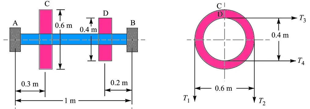
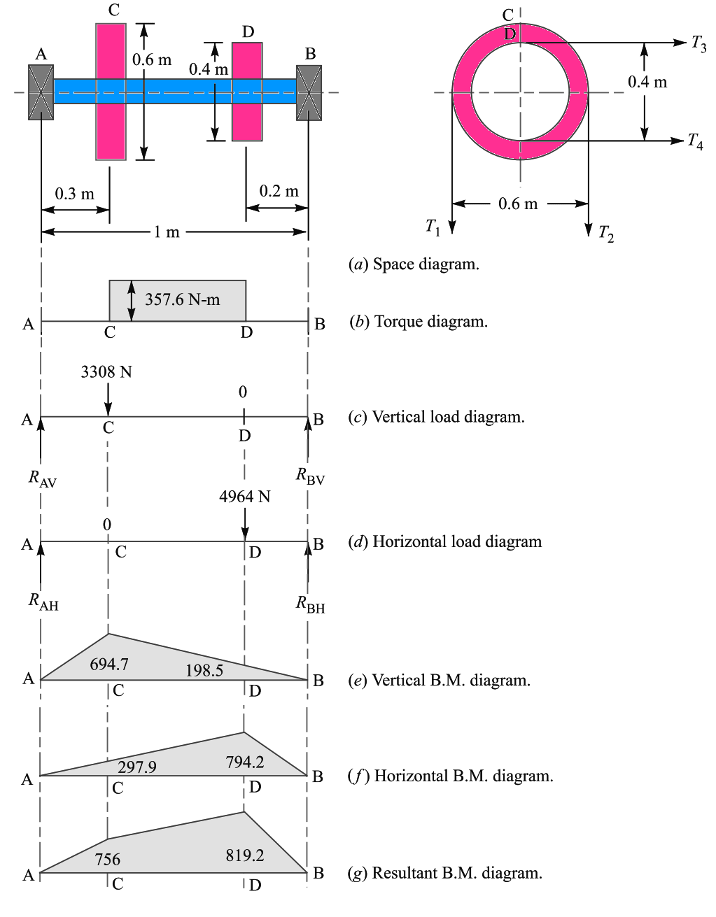
This torque has been represented on the below diagram part (a)
We know that diameter of the gear = No. of teeth on the gear × module (From here)
The radius of transmitting gear C = (TC × mC)/2 = (100 × 5)/2 = 250mm
Similarly the radius of pinion D = (TD × mD)/2 = (30 × 5)/2 = 75mm
We can make an assumption that the torque at C and D is the same.
Therefore tangential force on the gear C, acting downward,
FtC = T / RC = (716 × 103) / 250 = 2870N
Similarly the tangential force on the pinion D, acting horizontally,
FtD = T / RD= (716 × 103) / 75 = 9550N
These forces are represented in the schematic diagram part (c) and (d)

Now let us find the maximum bending moment for vertical and horizontal loading.
Finding Bending Moment for Vertical loading on Gear shaft
First of all, considering the vertical loading at C.
Let us say RAV and RBV be the reactions at the bearings A and B respectively.
We know that RAV + RBV = 2870 N
Taking moments about A, we can write
RBV × 750 = 2870 × 150
RBV = 2870 × 150 / 750
RBV = 574 N
Now let us find the RAV = 2870 – 574 = 2296 N
We know that Bending Moment at A and B will be MAV = MBV = 0
Bending Moment at C will be MCV = RAV × 150 = 2296 × 150 = 344400N-mm
Bending Moment at D will be MDV = RBV × 100 = 574 × 100 = 57400N-mm
The Bending Moment diagram for vertical loading is shown above diagram part (e).
Finding Bending Moment for Horizontal loading on Gear shaft
Now considering horizontal loading at D. Let RAH and RBH be the reactions at the bearings A and B respectively.
We know that
RAH + RBH = 9550 N
Taking moments about A, we get
RBH × 750 = 9550 (750 – 100)
RBH × 750 = 9550 × 650
RBH = 9550 × 650 / 750
RBH = 8277 N
Now let us find the RAH = 9550 – 8277 = 1273 N
We know that Bending Moment at A and B will be MAH = MBH = 0
Bending Moment at C will be MCH = RAH × 150 = 1273 × 150 = 190 950 N-mm
Bending Moment at D will be MDH = RBH × 100 = 8277 × 100 = 827 700 N-mm
The Bending Moment diagram for Horizontal loading is shown above diagram part (f).
Finding Resultant Bending Moments
Now we need to find the resultant bending moment at C,
MC =√((mcv)2+(mch)2) = √((344 400)2+(190 950)2) = 393790 N-mm
The resultant bending moment at at D
MD =√((mdv)2+(mdh)2) = √((57 400)2+(827 700)2) = 829690 N-mm
The resultant Bending Moment diagram is shown above diagram part (g).
From the above schematic diagram of bending moment, it is observed that the Bendig moment is maximum at D.
The Maximum bending moment M will be = MD = 829 690 N-mm
Calculating Shaft Diameter
Letus say d = Diameter of the shaft.
We know that the equivalent twisting moment if the shaft is subjected to the twisting moment and bending moment,

√ ((829 690)2+(716 103)2) = (π/16) × 54 × d3
1096 × 103 = 10.6 d3
d3 = 1096 × 103/10.6
d3 = 103.4 × 10³
d = 47
Let us take the shaft diameter as 50mm.
Similarly, if the shaft is subjected to fluctuating load or axial load, we can use the equivalent twisting moment equation mentioned in these articles respectively.
How to calculate the shaft diameter from the torque?
How to calculate Shaft Diameter under Twisting, Bending Moment, and Fluctuating?

To ensure the equipment is in good working order, it is important to calculate the shaft diameter from the torque based on the maximum amount of twists in the shaft. Thanks for sharing. That’s helpful!