Project Title: Designing of Microstrip Antenna for Wireless application by integrating Embedded and IoT
A Final year project on “Designing of Microstrip Antenna for Wireless application by integrating Embedded and IoT” was submitted by Bhavendra chowdary Swarna (from Lovely Professional University, India)to extrudesign.com.

ABSTRACT
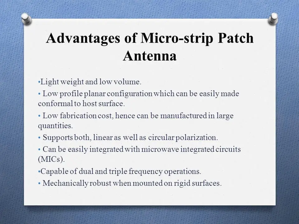
The project is about designing a microstrip antenna using different modes of feeding techniques and integrating it with embedded and IoT for wireless applications. microstrip antenna has several advantages compared to other antennas. This type of antenna is lightweight, has low volume and has thin profile configurations, which can be made conformal. The cost of fabrication is also low and can be in large quantities. This project will discuss the microstrip antenna. The aim of this project is to design a microstrip antenna. Here we are integrating Embedded and IoT. We are using Embedded for data transmission via IoT(Wifi-module). Finally, the main objective of our project is to design a microstrip antenna and Transfer the data using wireless transmission as a medium and store the data.
Here we used computer simulation technology(CST) Software for designing and analyzing antenna
The microstrip antenna is designed with the dielectric substrate as Rogers RT/droid 5880(tm) with ɛr = 2.2. This antenna will work on IEEE 802.11 WLAN, 2.4 GHz band. The antenna is optimized to improve the performance measures like gain, return loss and efficiency.
Computer Simulation Technology (CST) microwave studio software is used to analyze the radiation pattern of the antenna before fabricating the antenna. Vector Network Analyzer (VNA) was used to measure the manufactured fabricated antenna to obtain the measurement result. The simulation and measurement results show a few differences for both of the material substrates. A comparison between simulation and measurement results has been made.
INTRODUCTION
In radio engineering, an antenna is an interface between radio waves propagating through space and electric currents moving in metal conductors, used with a transmitter or receiver.
HOW TRANSMISSION OCCURS :
In transmission, a radio transmitter supplies an electric current to the antenna’s terminals, and the antenna radiates the energy from the current as electromagnetic waves (radio waves). In reception, an antenna intercepts some of the power of a radio wave in order to produce an electric current at its terminals, which is applied to a receiver to be amplified.
“Antennas are essential components of all radio equipment.”
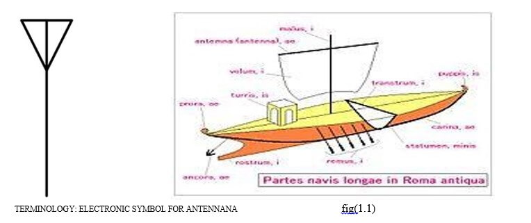
The words antenna and aerial are used interchangeably. Occasionally the equivalent term “aerial” is used to specifically mean an elevated wire antenna
In Italian, a tent pole is known as an antenna centrale, and the pole with the wire was simply called an antenna. Until then wireless radiating transmitting and receiving elements were known simply as “terminals”.
The antenna may refer broadly to an entire assembly including support structure, enclosure (if any), etc., in addition to the actual functional components.
A receiving antenna may include not only the passive metal receiving elements but also an integrated preamplifier or mixer, especially at and above microwave frequencies.
OVERVIEW
Antennas are required by any radio receiver or transmitter to couple its electrical connection to the electromagnetic field. Radio waves are electromagnetic waves that carry signals through the air (or through space) at the speed of light with almost no transmission loss.
Antennas can be classified as omnidirectional, radiating energy approximately equally in all directions, or directional, where energy radiates more along one direction than others. (Antennas are reciprocal, so the same effect occurs for the reception of radio waves.) A completely uniform omnidirectional antenna is not physically possible. Some antenna types have a uniform radiation pattern in the horizontal plane but send little energy upward or downward. A “directional” antenna usually is intended to maximize its coupling to the electromagnetic field in the direction of the other station.
In order to contact a remote area, the wiring has to be laid down throughout the whole route along the valleys, the mountains, the tedious paths, the tunnels etc., to reach the remote location.
The evolution of wireless technology has made this whole process very simple.
“Antenna is the key element of this wireless Technology”
The basic communication parameters are discussed in this paper to have a better idea about wireless communication using antennas.
The parameters are :
- Frequency
- Wavelength
- Impedance matching
- VSWR & reflected power
- Bandwidth
- Percentage bandwidth
- Radiation Intensity
1. Frequency:
According to the standard definition, “The rate of repetition of a wave over a particular period of time, is called as frequency.”
Simply, frequency refers to the process of how often an event occurs. A periodic wave repeats itself after every ‘T’ seconds (time period). The frequency of periodic waves is nothing but the reciprocal of the time period (T).
Mathematical Expression:
Mathematically, it is written as shown below.
f=1/T
Where
- f is the frequency of periodic wave.
- T is the time period at which the wave repeats.
Units:
The unit of frequency is Hertz, abbreviated as Hz. Figure:(2)
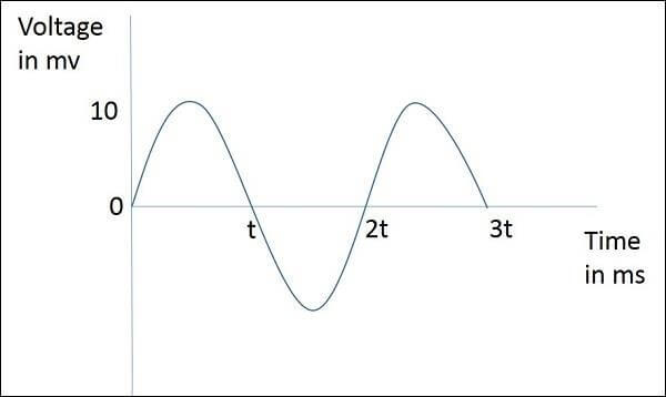
Which is plotted here for Voltage in millivolts against time in milliseconds. This wave repeats after every 2t milliseconds. So, time period, T=2t milliseconds and frequency, f=1/2T kHz.
2. Wavelength:
According to the standard definition, “The distance between two consecutive maximum points (crests) or between two consecutive minimum points (troughs) is known as the wavelength.”
Simply, the distance between two immediate positive peaks or two immediate negative peaks is nothing but the length of that wave. It can be termed as the Wavelength.
The wavelength (λ) and amplitude are denoted in the figure. The higher the frequency, the lesser will be the wavelength and vice versa.
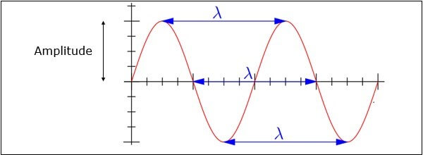
The following figure(3) shows a periodic waveform.
Mathematical Expression
The formula for wavelength is, λ=c/f
Where
- λ is the wavelength
- c is the speed of light (3
1083
108 meters/second)
- f is the frequency
Units
The wavelength λ is expressed in the units of length such as meters, feet or inches. The commonly used term is meters.
3. Impedance Matching:
According to the standard definition, “The approximate value of the impedance of a transmitter, when equals the approximate value of the impedance of a receiver, or vice versa, it is termed as Impedance matching.”
Impedance matching is necessary between the antenna and the circuitry. The impedance of the antenna, the transmission line, and the circuitry should match so that maximum power transfer takes place between the antenna and the receiver or the transmitter.
4. Necessity of Matching:
A resonant device is one, which gives better output at a certain narrow band of frequencies. Antennas are such resonant devices whose impedance if matched, delivers a better output.
- The power radiated by an antenna, will be effectively radiated, if the antenna impedance matches the free space impedance.
- For a receiver antenna, antenna’s output impedance should match with the input impedance of the receiver amplifier circuit.
- For a transmitter antenna, antenna’s input impedance should match with transmitter amplifier’s output impedance, along with the transmission line impedance.
Units:
The unit of impedance (Z) is Ohms.
5. VSWR & Reflected Power:
According to the standard definition, “The ratio of the maximum voltage to the minimum voltage in a standing wave is known as Voltage Standing Wave Ratio.” If the impedance of the antenna, the transmission line and the circuitry do not match with each other, then the power will not be radiated effectively. Instead, some of the power is reflected back.
The key features are −
- The term, which indicates the impedance mismatch is VSWR.
- VSWR stands for Voltage Standing Wave Ratio. It is also called as SWR.
- The higher the impedance mismatch, the higher will be the value of VSWR.
- The ideal value of VSWR should be 1:1 for effective radiation.
- Reflected power is the power wasted out of the forward power. Both reflected power and VSWR indicate the same thing.
6. Bandwidth:
According to the standard definition, “A band of frequencies in a wavelength, specified for the particular communication, is known as bandwidth.”
The signal when transmitted or received is done over a range of frequencies. This particular range of frequencies is allotted to a particular signal, so that other signals may not interfere in its transmission.
- Bandwidth is the band of frequencies between the higher and lower frequencies over which a signal is transmitted.
- The bandwidth once allotted, cannot be used by others.
- The whole spectrum is divided into bandwidths to allot to different transmitters.
The bandwidth, which we just discussed can also be called Absolute Bandwidth.
7. Percentage Bandwidth:
According to the standard definition, “The ratio of absolute bandwidth to the centre frequency of that bandwidth can be termed as percentage bandwidth.”
The particular frequency within a frequency band, at which the signal strength is maximum, is called the resonant frequency. It is also called as centre frequency (fC) of the band.
- The higher and lower frequencies are denoted as fH and fL respectively.
- The absolute bandwidth is given by- fH – fL.
- To know how wider the bandwidth is, either fractional bandwidth or percentage bandwidth has to be calculated.
Mathematical Expression:
The Percentage bandwidth is calculated to know how much frequency variation either a component or a system can handle.
Percentage bandwidth = (𝑓𝐻 – 𝑓𝐿)/𝑓𝑐
Where
- 𝑓𝐻 is higher frequency
- 𝑓𝐿 is lower frequency
- 𝑓𝑐 is center frequency
The higher the percentage bandwidth, the wider will be the bandwidth of the channel.
8.Radiation Intensity:
“Radiation intensity is defined as the power per unit solid angle”
Radiation emitted from an antenna that is more intense in a particular direction indicates the maximum intensity of that antenna. The emission of radiation to a maximum possible extent is nothing but radiation intensity.
Mathematical Expression
Radiation Intensity is obtained by multiplying the power radiated with the square of the radial distance.
U = 𝑟2 × Wrad
Where
- U is the radiation intensity
- r is the radial distanceNNnn
- Wrad is the power radiated.
The above equation denotes the radiation intensity of an antenna. The function of radial distance is also indicated as Φ.
Units
The unit of radiation intensity watts/radian2.
Wireless communication is done in the form of waves. Hence, we need to look at the properties of waves in communications.
In this paper, we are going to learn the basic concepts of antennas, specifications and different types of antennas. They are many types of antennas depending upon
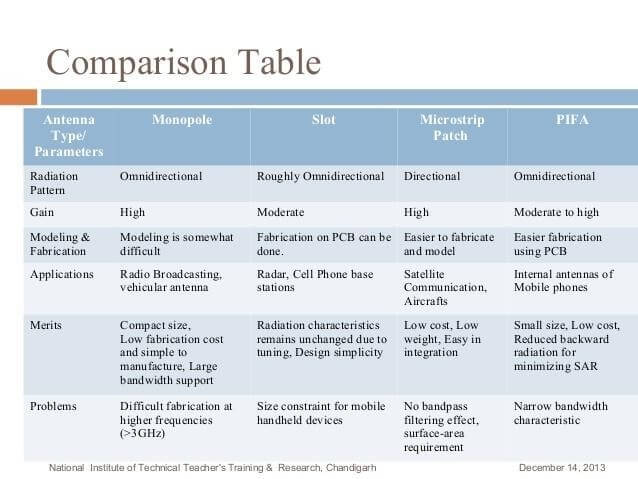
MICROSTRIP ANTENNA
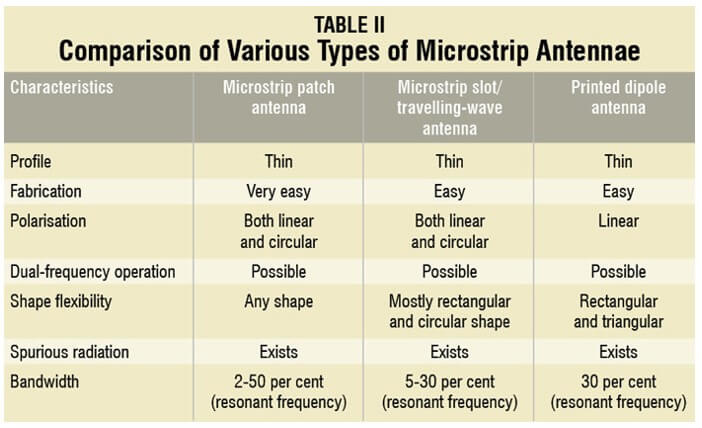
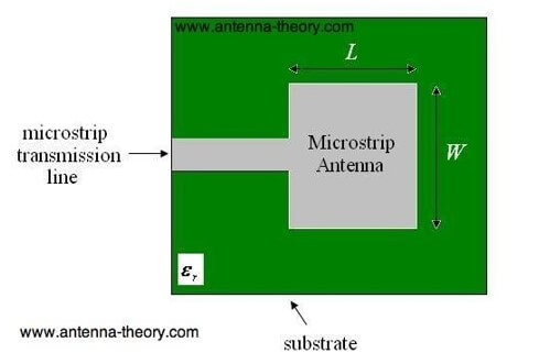
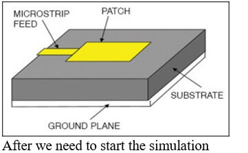
In telecommunication, a microstrip antenna (also known as a printed antenna) usually means an antenna fabricated using microstrip techniques on a printed circuit board(PCB). It is a kind of internal antenna. They are mostly used at microwave frequencies. An individual microstrip antenna consists of a patch of metal foil of various shapes (a patch antenna) on the surface of a PCB (printed circuit board), with a metal foil ground plane on the other side of the board. Most microstrip antennas consist of multiple patches in a two-dimensional array. The antenna is usually connected to the transmitter or receiver through foil microstrip transmission lines. The radiofrequency current is applied (or in receiving antennas the received signal is produced) between the antenna and ground plane. Microstrip antennas have become very popular in recent decades due to their thin planar profile which can be incorporated into the surfaces of consumer products, aircraft and missiles; their ease of fabrication using printed circuit techniques; the ease of integrating the antenna on the same board with the rest of the circuit, and the possibility of adding active devices such as microwave integrated circuits to the antenna itself to make active antennas.
RECTANGULAR PATCH
1. The most commonly employed microstrip antenna is a rectangular patch that looks like a truncated microstrip transmission line. It is approximately one-half wavelength long. When air is used as the dielectric substrate, the length of the rectangular microstrip antenna is approximately one-half of a free-space wavelength. As the antenna is loaded with a dielectric as its substrate, the length of the antenna decreases as the relative dielectric constant of the substrate increases. The resonant length of the antenna is slightly shorter because of the extended electric “fringing fields” which increase the electrical length of the antenna slightly. An early model of the microstrip antenna is a section of microstrip transmission line with equivalent loads on either end to represent the radiation loss.
FEEDING TECHNIQUES OF MICROSTRIP ANTENNA:
The patch antennas may be powered by many methods. The processes feeding are categorized in two methods: • In category contacting, the feeding technique is powered by means of a connecting element such as a microstrip line into the radiating patch. • Without the contact category, a transfer of power between the microstrip line and radiating element is performed with the electromagnetic field coupling. The most famous feeding techniques employed in the microstrip patch antenna are coaxial probe, feeding technique with microstrip line and aperture or proximity coupling methods.
A. Feeding Techniques
In this kind of feeding process (Fig.2), the edge of the microstrip patch is connected directly to a conducting strip. This feeding method offers the benefit that the conducting line can have the opportunity of being engraved on the same substrate of patch antenna providing a planar shape. The width of conducting element is smaller as compared to the patch antenna.
B . Coaxial Probe Feeding Techniques
The outside conductor of a coaxial connector is attached at the ground plane, while the inside is extended across the dielectric and is welded at the radiating element antenna. However, the disadvantage of this technique is difficult to model and produce à narrow bandwidth. Figure 3 show this type of feed technique. Fig.3. Coaxial Probe Feed
C.Feeding Techniques With Proximity coupled
This feeding technique (Fig. utilized two dielectric substrates in order that the feed line, firstly, is between two substrates and on the other hand the radiating element is on top of the upper substrate.
D. Aperture coupled feed
In this type of feed technique, a microstrip feed line is separated by the ground plane to the radiating patch. The feed line and the radiating element is coupled through an aperture or a slot in the ground plane. The variations in the coupling will depend on the width and length of the slot to improve the simulation result of bandwidths and return losses. The slot is usually centred under the radiating element.
About CST Software:
CST Studio Suite® is a high-performance 3D EM analysis software package for designing, analyzing and optimizing electromagnetic (EM) components and systems.
Electromagnetic field solvers for applications across the EM spectrum are contained within a single user interface in CST Studio Suite. The solvers can be coupled to perform hybrid simulations, giving engineers the flexibility to analyze whole systems made up of multiple components in an efficient and straightforward way. Co-design with other SIMULA Products allows EM simulation to be integrated into the design flow and drives the development process from the earliest stages.
Common subjects of EM analysis include the performance and efficiency of antennas and filters, electromagnetic compatibility and interference (EMC/EMI), exposure of the human body to EM fields, electro-mechanical effects in motors and generators, and thermal effects in high-power devices.
CST Studio Suite is used in leading technology and engineering companies around the world. It offers a considerable product to market advantages, facilitating shorter development cycles and reduced costs. Simulation enables the use of virtual prototyping. Device performance can be optimized, potential compliance issues identified and mitigated early in the design process, the number of physical prototypes required can be reduced, and the risk of test failures and recalls are minimized.
CST Studio suite 2019 Crack Download CST Microwave Studio full Crack Download clip art adobe after effects CST Studio Suite 2019 Full Crack Free Software Full Version CST Studio Suite 2018 free download the latest version for windows. The CST Studio Suite 2019 is a full offline installer setup for windows 32bit and 64-bit operating systems.
This is a stunning application that offers exact and exact answers for delivering electromagnetic structures. The designers put the long periods of research to grow such an immaculate instrument for the specialists.
It enables the client to build up the abnormal state structuring and recurrence improving circuits that are straightforward and actualize on the field.

This is a superb program that offers the astonishing highlights of structuring. You Can Also Download Liquid Studio 2019 Free Download.
The client will figure out how to draw the grand structures of control circuits, gather with the expansion of model and electromagnetic frameworks in 3D.
You can likewise reenact the numeric in electromagnetic fields with any further procedure. It gives the coordinated condition in which you can without much of a stretch play out every one of the functionalities. The client is permitted to use every one of the assets which are given in the interface.
It let them make intricate and huge plans to enable the client to reproduce the numeric in electromagnetic fields. This program offers the consistent condition in which you can without much of a stretch play out all the usefulness in a viable way.

The client will be mastered on framework get together, multi-usefulness, and displaying of the circuits. It contains diverse circuits which are there and profoundly valuable for designing purposes.
There are different other helpful preferences of the product which incorporates the shorter advancement cycle, item improvement, and virtual prototyping. The program offers numerous interfaces in the archives.
It contains the message windows, variable devices and parameters for the best execution. It underpins the transmission of parameters and is competent to naturally install and interface the servers. The program will bolster you in programmed streamlining and venture the boar
Feature of CST Studio Suite 2019
Some of the presently features of CST Studio Suite 2019.
- This is the wonderful tool for electromagnetic designs.
- Delivers the flawless services to the clients.
- You can utilize all the resources in the effective pattern.
- Handle the big and complex designs.
- It supports the auto-slide power point creation and output layout animation.
System requirements of CST Studio Suite 2019 Free Download:
Prior to downloading CST Studio Suite 2019 you must ensure that your system fulfills the minimum system requirements.
- Supporting Windows: Windows 7/8/8.1//11
- Processor: Intel Pentium 4
- RAM: 4 GB
- Required Hard Disk Space: 4 GB
Technical details of CST Studio Suite 2019:
- Software Name: CST Studio Suite 2019
- File Size: 3.2 GB
- Developer: CST
- Compatible with: 32-bit and 64-bit Computer Architecture
Design of Microstrip Antenna on CST:
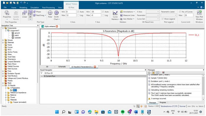
After installation of CST software in our system we need to select the Microwaves and Rf/Optical template then Antenna then Planar workflow then frequency domain in solvers after we need select units then we need to give minimum and maximum frequency.
I have given frequency as 8GHZ and 12GHZ and defined at 8,10,11.4,12.





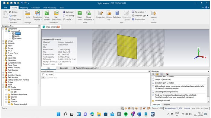
1. For GROUND:
I have taken dimensions as -9 to +9 on x which is the length
And -9 to 9 on y which is the width
And for z 0 to 0.018 for copper annealed material.
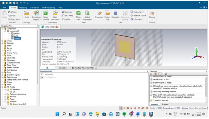
2. Substate:
I have taken dimensions as -9 to+9 on x which is the length
And -9 to 9 on y which is the width
And for z 0.018 to 0.818 for PTFE(lossy) material.
3. patch:
I have taken dimensions as -5 to +5 on x which is the length
And -4.85 to +4.85 on y which is the width
And for z 0.818 to 0.836 for copper annealed material.
4. Feedline:
I have taken dimensions as -1.2 to +1.2 on x which is the length
And -9 to -7.8 on y which is the width
And for z 0.818 to 0.836 for copper
5.Transform: (lambda/4)
I have taken dimensions as -0.18 to +0.18 on x which is the length
And -4.85 to +4.85 on y which is the width
And for z -7.8 to -4.85 for copper annealed material.
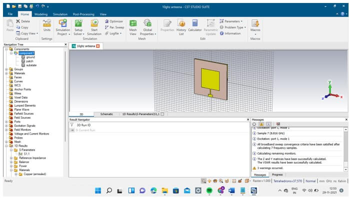
After we need to March patch, feedline, transform
Firstly we need to march feedline and transform by using Booleans add the tool after getting a result we need to march with a patch using Booleans add tool.

APPLICATIONS:
CST is software used for electromagnetic design and analysis in the high-frequency range by researchers.
Due to its compatibility, CST can solve any high-frequency field problem, and thus, it remains the top choice of scientific researchers.
Conclusion:
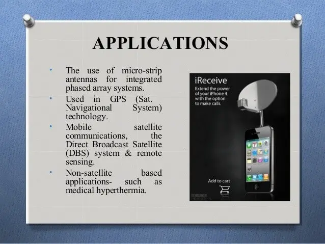
Microstrip patch antennas are rapidly growing because of their low profile, lightweight, and compact size which can also be used in various domains of communication such as telecommunications, broadcasting, and satellite communication technologies. Different positions of the slots are being checked and among that slot etched on the ground is found to give better results. The gain has been improved by truncating the edges of the patch. The antenna is thin and compact in size by using a low dielectric constant substrate making it suitable for IoT applications. The main theme of the project considering all the literature and references is to design a microstrip antenna that can be used for communication. The project in brief was to receive, process a signal and share or save the processed information to another device by using any communication modules and save it using a black box. This type of project helps in sending the information during unconventional conditions and its portability and simple mechanism make it much comfortable to use in different domains.
REVIEW OF LITERATURE
1.Circular Polarization Reconfigurable Wideband E-Shaped Patch Antenna for Wireless Applications
A polarization reconfigurable E-shaped patch antenna with wideband performance is proposed in this communication. The antenna is capable of switching its polarization from right-hand circular polarization (RHCP) to left-hand circular polarization (LHCP) and vice versa. Its structure is simple and consists of a single-layer single-feed E-shaped patch and two RF switches placed at appropriate locations in the slots. The design targets the WLAN IEEE 802.11 b/g frequency band (2.4-2.5 GHz) being used in various wireless communication systems. Full-wave simulation is used for the antenna analysis, and a prototype of the antenna with an integrated DC biasing circuit has been fabricated and tested. Good agreement is obtained between simulated and measured results. The antenna exhibits a 7% effective bandwidth from 2.4 GHz to 2.57 GHz
with a 8.7 dB maximum gain. The antenna radiation symmetry is maintained upon switching between the two circular polarization modes.
2.Optimized Microstrip Antenna Arrays for Emerging MillimeterWave Wireless Applications
Two compact planar antennas operating in the unlicensed 60 GHz frequency band are presented based on the physical layer specifications of IEEE 802.15.3c and ECMA 387 standards for different classes of wireless applications. Each antenna is an array of 2 × 2 microstrip antennas covering at least two channels of the 60 GHz spectrum. The first antenna is optimized to achieve the highest gain, while the second antenna is optimized to give the largest beamwidth. The maximum measured radiation gain of the first antenna is 13.2 dBi. The measured beamwidth and gain of the second antenna are 76 ° and 10.3 dBi, respectively. The areas of these two antennas are only 0.25 and 0.16 cm 2. The variation of radiation gain of each antenna over the frequency range of 57-65 GHz is less than 1 dB.
3.Compact Circularly Polarized Asymmetrical Fractal Boundary Microstrip Antenna for Wireless Applications
Compact fractal boundary microstrip antenna is proposed for circular polarization (CP). By replacing the sides of a square patch with asymmetrical pre fractal curves, two orthogonal modes are excited about CP operation. The structure is asymmetric along the principal axes (x, y). The indentation parameter of the fractal boundary curve is optimized to design compact CP antennas. Experimental results show that 10-dB return loss and 3-dB axial-ratio bandwidths of the proposed fractal boundary Ant 2 are 162 and 50 MHz, respectively, at an operating frequency of around 2540 MHz. Results show that an excellent CP is achieved with a single probe feed, besides reduction in the antenna size by applying fractal boundary concept.
4. 2.45 GHz Microstrip Patch Antenna with Defected Ground Structure for Bluetooth
In this paper, a rectangular microstrip patch antenna with DGS has been analyzed and simulated for wireless applications. The proposed antenna has been simulated at a 2.45 GHz frequency. This compact antenna is fed by Quarter Transformer feeding. This type of feeding is mostly used for impedance matching purposes. The antenna is simulated by the software HFSS. HFSS, a high-frequency structure simulator is employed to analyze the proposed antenna and simulated results on return loss, the E and H plane radiation pattern and polar plot gain are presented. The resultant antenna with Defected Ground Structure has improved in parameters performance.
5. Low cost Microstrip patch Antenna array for Wireless Communications by Gazala Pravin, A. K. Rastogi
In this authors explained about a Single-band E-shaped microstrip Patch Antenna array has been designed for high-speed wireless local area networks (IEEE
802.11a standard) and other wireless communication systems covering this frequency band like
WiMax and C-band with the mounted on
a low-cost FR-4 substrate. FR-4 whose relative permeability is 4.4 and a loss tangent of 0.02 is used for a proposed design. A simulation tool, Sonnet Suites, a planar 3D electromagnetic simulator is used in this work.
6. Design and Analysis of Microstrip Patch Antenna for Wireless Communication by Ranjan Mishra, Raj Gaurav Mishra, R. K. Chaurasia, Amit Kumar Shrivastava
In this paper, the authors explained that the microstrip antenna required for wideband correspondence ought to be lightweight, easy to fabricate and smaller in size. The present situation plan is to create a simple geometrical shaped structure of the microstrip antenna, which would give decent broadband. The paper presents the design analysis of rectangular and square-shaped microstrip antennas. Both the antennas used microstrip lines for feeding purposes. The square-shaped microstrip antenna is offering wider bandwidth as compared to rectangular microstrip and sufficient return loss. The compact antenna is meant for its operation in X band of frequency. The proposed microstrip antenna is showing a wide bandwidth of 500 MHz with a high return loss of -24 dB. This high bandwidth provides its usefulness in many wideband utilities in the X- band.
7. Flexible Wireless Antenna Sensor
The principle of the patch antenna as a sensing element and the wireless interrogation of the antenna sensors are presented first, followed by the description of the antenna design and fabrication using flexible film components. The applications of the flexible antenna sensor for wireless strain sensing and crack detection are presented. The design and testing of inserting a flexible layer to improve the reliability of the flexible antenna sensor is also discussed. Because the flexible antenna sensors can be wirelessly interrogated with ultra-low power consumption and can be frequency division multiplexed, the complexity of implementing a large sensor array is greatly reduced.
8.Microstrip patch antenna Miniaturisation techniques
The microstrip patch antenna (MPA) has been in use and has been studied extensively during the past three decades. This antenna, which consists of a metallic patch printed on a dielectric substrate over a ground plane, offers several advantages including ease of design and fabrication; low profile and planar structure; and ease of integration with circuit elements. The minimum dimension of a conventional MPA is in the order of half a wavelength. In recent years, with the advent of new standards and compact wireless devices, there has been a need to reduce the size of this type of antenna. This study discusses some of the principal techniques
9. Compact Broadband Slotted Rectangular Microstrip Antenna
By integrating a half-U-slot and a rectangular slot inside the RMSA, a new compact broadband configuration is proposed. The proposed RMSA gives more than twice the BW compared to the BW given by a single half-U-slot-cut RMSA or RMSA with the rectangular slot. The MSA has a gain of more than 7 dBi over the entire BW with the broadside radiation pattern. A good agreement is obtained between the simulated and measured input impedance, gain, and radiation pattern plots.
10. Microstrip Stacked Patch Antenna With Circular Polarization for 2.45-GHz Mobile RFID Reader
A compact and broadband antenna for a 2.45-GHz RFID reader was presented. Based on the matching condition with the S-shaped IMN technology, the compact antenna was optimized to obtain high performance. Excellent matching and optimal performance of the fabricated antenna were verified by experiment as well. The optimized antenna had a peak gain of 6.32dBi, a VSWR<2 impedance bandwidth of larger than 15.1%, a 3-dB beamwidth of more than 91°, and an effective antenna efficiency of larger than 87%. The antenna also had a compact size of 58×58×11 mm3. The antenna had an excellent performance of high gain and wide bandwidth. Hence, it also has the potential to be used in other wireless communication systems, such as WiFi.
REFERENCES :
- M. A. Kossel, R. Kung, H. Benedickter, W. Bachtold, “An active tagging system using circular polarization modulation”, IEEE Trans. Microw. Theory Tech., vol. 47, no. 12, pp. 2242-2248, Dec. 1999.
- Graf, Rudolf F., ed. (1999). “Antenna”. Modern Dictionary of Electronics. Newnes. p. 29. ISBN 978-0750698665. –introduction
- Lee, Kai Fong,; Luk, Kwai Man (2011). Microstrip Patch Antennas. World Scientific. pp. 8–12. ISBN 184816453X.
- C. Karnfelt, P. Hallbjorner, H. Zirath, A. Alping, “High gain active microstrip antenna for 60-GHz WLAN/WPAN applications”, IEEE Trans. Microw. Theory Tech., vol. 54, no. 6, pp. 2593-2603, Jun. 2006
- P. C. Sharma, K. C. Gupta, “Analysis and optimized design of single feed circularly polarized microstrip antennas”, IEEE Trans. Antennas Propag., vol. AP-31, no. 6, pp. 949-955, Nov. 1983.
- Ashwini K. Arya, M. V. Kartikeyan, A .Patnaik, “Defected Ground Structure in the perspective of Microstrip antenna,” Frequenz, Vol.64, Issue5-6, pp.79-84 , Oct 2010.
- Huang H. Flexible wireless antenna sensor: A review. IEEE sensors journal. 2013 Jan 24;13(10):3865-72.
- Khan, Muhammad Umar, Mohammad Said Sharawi, and Raj Mittra. “Microstrip patch antenna miniaturisation techniques: a review.” IET Microwaves, Antennas & Propagation 9.9 (2015): 913-922.
- Deshmukh, A.A. and Ray, K.P., 2009. Compact broadband slotted rectangular microstrip antenna. IEEE antennas and wireless propagation letters, 8, pp.1410-1413.
- Wu, Tingqiang, Hua Su, Liyun Gan, Huizhu Chen, Jingyao Huang, and Huaiwu Zhang. “A compact and broadband microstrip stacked patch antenna with circular polarization for 2.45-GHz mobile RFID reader.” IEEE Antennas and Wireless Propagation Letters 12 (2013): 623-626.
Credit: This project “Designing of Microstrip Antenna for Wireless application by integrating Embedded and IoT” was completed by Bhavendra chowdary Swarna under guidence of Dr. Parulpreet Singh from Electronics and Communication Engineering Department of Lovely Professional University, India.

Leave a Reply