A brake is a device by means of which artificial frictional resistance is applied to a moving machine member, in order to retard or stop the motion of a machine. In the process of performing this function, the brake absorbs either the kinetic energy of the moving member or potential energy given up by objects being lowered by hoists, elevators, etc. In the previous article, we discussed how we can calculate the energy absorbed by a brake. In this article let us see how we can calculate the Heat Dissipation during Braking.

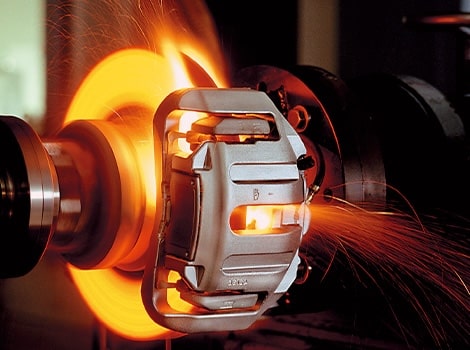
As we mentioned above that the brake is used to retard or stop the motion of a machine. This action is called Braking. In the process of braking, the brake absorbs either the kinetic energy of the moving member or potential energy given up by objects being lowered by hoists, elevators etc. The energy absorbed by brakes is dissipated in the form of heat. This heat is dissipated in the surrounding air (or water which is circulated through the passages in the brake drum) so that excessive heating of the brake lining does not take place.
The design or capacity of a brake depends upon the following factors :
- The unit pressure between the braking surfaces
- The coefficient of friction between the braking surfaces
- The peripheral velocity of the brake drum
- The projected area of the friction surfaces
- The ability of the brake to dissipate heat is equivalent to the energy being absorbed.
The major functional difference between a clutch and a brake is that a clutch is used to keep the driving and driven member moving together, whereas brakes are used to stop a moving member or to control its speed.
Heat Dissipation during Braking
The energy absorbed by the brake and transformed into heat must be dissipated to the surrounding air in order to avoid excessive temperature rise of the brake lining. The temperature rise depends upon the mass of the brake drum, the braking time and the heat dissipation capacity of the brake.

The highest permissible temperatures recommended for different brake lining materials are given as follows:
- For leather, fibre and wood facing = 65 – 70°C
- For asbestos and metal surfaces that are slightly lubricated = 90 – 105°C
- For automobile brakes with asbestos block lining = 180 – 225°C
Since the energy absorbed (or heat generated) and the rate of wear of the brake lining at a particular speed are dependent on the normal pressure between the braking surfaces, therefore it is an important factor in the design of brakes.
The permissible normal pressure between the braking surfaces depends upon the material of the brake lining, the coefficient of friction and the maximum rate at which the energy is to be absorbed.
The energy absorbed or the heat generated is given by
E = Hg = μ.RN.v
E = μ . p . A . v (in J/s or watts)
Where
μ = Coefficient of friction,
RN = Normal force acting at the contact surfaces, in newtons,
p = Normal pressure between the braking surfaces in N/m2,
A = Projected area of the contact surfaces in m2
v = Peripheral velocity of the brake drum in m/s.
The heat generated may also be obtained by considering the amount of kinetic or potential energies which is being absorbed. In other words,
Hg = EK + EP
EK = Total kinetic energy absorbed
EP = Total potential energy absorbed
The heat dissipated (Hd) may be estimated by
Hd = C (t1 – t2) Ar
Where
C = Heat dissipation factor or coefficient of heat transfer in W /m2 / °C
t1 – t2 = Temperature difference between the exposed radiating surface and the surrounding air in °C,
Ar = Area of radiating surface in m2.
The value of C may be of the order of 29.5 W / m2 /°C for a temperature difference of 40°C and increase up to 44 W/m2/°C for a temperature difference of 200°C.
The expressions for the heat dissipated are quite approximate and should serve only as an
indication of the capacity of the brake to dissipate heat. The exact performance of the brake should be determined by test.
It has been found that 10% to 25% of the heat generated is immediately dissipated to the surrounding air while the remaining heat is absorbed by the brake drum causing its temperature to rise.
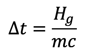
The rise in temperature of the brake drum is given by

Where
∆ t = Temperature rise of the brake drum in °C
Hg = Heat generated by the brake in joules,
m = Mass of the brake drum in kg, and
c = Specific heat for the material of the brake drum in J/kg °C.
In brakes, it is very difficult to precisely calculate the temperature rise. In preliminary design analysis, the product p.v is considered in place of temperature rise. The experience has also shown that if the product p.v is high, the rate of wear of brake lining will be high and the brake life will be low. Thus the value of p.v should be lower than the upper limit value for the brake lining to have reasonable wear life.
The following table shows the recommended values of p.v as suggested by various designers for different types of service.
| S.No. | Type of service | Recommended value of p.v in N-m/m2 of projected area per second |
| 1. | Continuous application of load as in lowering operations and poor dissipation of heat. | 0.98 × 10⁶ |
| 2. | Intermittent application of load with comparatively long periods of rest and poor dissipation of heat | 1.93 × 10⁶ |
| 3. | For continuous application of load and good dissipation of heat as in an oil bath. | 2.9 × 10⁶ |
With these relations we can estimate the Heat Dissipation during Braking. Let us know what you think about this article in the comment section below.
Let us also discuss the different material characteristics for Brake Lining.
Materials for Brake Lining
The material used for the brake lining should have the following characteristics:
- It should have high coefficient of friction with minimum fading. In other words, the coefficient of friction should remain constant over the entire surface with change in temperature.
- It should have low wear rate.
- It should have high heat resistance.
- It should have high heat dissipation capacity.
- It should have low coefficient of thermal expansion.
- It should have adequate mechanical strength.
- It should not be affected by moisture and oil.
The materials commonly used for facing or lining of brakes and their properties are shown in the following table.
| Material for braking lining | Coefficient of friction ( μ ) | Allowable pressure (p) | ||
| Dry | Greasy | Lubricated | N/mm2 | |
| Cast iron on cast iron Bronze on cast iron Steel on cast iron Wood on cast iron Fibre on metal Cork on metal Leather on metal Wire asbestos on metal Asbestos blocks on metal Asbestos on metal Metal on cast iron | 0.15 – 0.2 – 0.20 – 0.30 0.20 – 0.35 – 0.35 0.3 – 0.5 0.35 – 0.5 0.40 – 0.48 – – | 0.06 – 0.10 0.05 – 0.10 0.07 – 0.12 0.08 – 0.12 0.10 – 0.20 0.25 – 0.30 0.15 – 0.20 0.25 – 0.30 0.25 – 0.30 – – | 0.05 – 0.10 0.05 – 0.10 0.06 – 0.10 – – 0.22 – 0.25 0.12 – 0.15 0.20 – 0.25 – 0.20 – 0.25 0.05 – 0.10 | 1.0 – 1.75 0.56 – 0.84 0.84 – 1.4 0.40 – 0.62 0.07 – 0.28 0.05 – 0.10 0.07 – 0.28 0.20 – 0.55 0.28 – 1.1 1.4 – 2.1 1.4 – 2.1 |

Leave a Reply