A brake is a device by means of which artificial frictional resistance is applied to a moving machine member, in order to retard or stop the motion of a machine. In the process of performing this function, the brake absorbs either the kinetic energy of the moving member or potential energy given up by objects being lowered by hoists, elevators, etc. In the previous articles, we discussed how we can calculate the energy absorbed by a brake and Heat Dissipation during Braking. We also discussed the different types of Brakes in the previous article. Let us discuss the Band and Block Brake in detail.
As we mentioned above that the brake is used to retard or stop the motion of a machine. This action is called Braking. In the process of braking, the brake absorbs either the kinetic energy of the moving member or potential energy given up by objects being lowered by hoists, elevators, etc. The energy absorbed by brakes is dissipated in the form of heat. This heat is dissipated in the surrounding air (or water which is circulated through the passages in the brake drum) so that excessive heating of the brake lining does not take place.
The design or capacity of a brake depends upon the following factors:
- The unit pressure between the braking surfaces
- The coefficient of friction between the braking surfaces
- The peripheral velocity of the brake drum
- The projected area of the friction surfaces
- The ability of the brake to dissipate heat is equivalent to the energy being absorbed.
The major functional difference between a clutch and a brake is that a clutch is used to keep the driving and driven member moving together, whereas brakes are used to stop a moving member or to control its speed.
We also solved an example problem to stop A vehicle of mass 1200 kg moving down the hill at a slope of 1:5. by finding how much amount of Braking Torque is required to stop the vehicle in the previous article.
Band and Block Brake
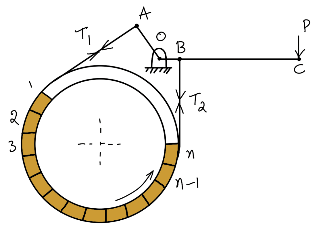
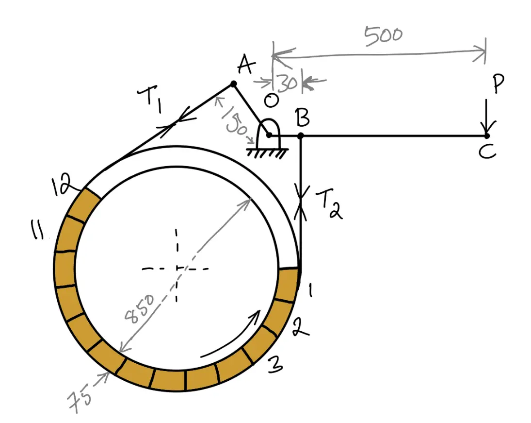
The band brake may be lined with blocks of wood or other material, as shown in the following figure. The friction between the blocks and the drum provides braking action. Let there be an ‘n’ number of blocks, each subtending an angle 2 θ at the center and the drum rotates in an anticlockwise direction.
Let
T1 = Tension in the tight side,
T2 = Tension in the slack side,
μ = Coefficient of friction between the blocks and drum,
T1‘ = Tension in the band between the first and second block,
T2‘ & T3‘ = Tensions in the band between the second and third block, between the third and fourth block, etc.
Consider one of the blocks (say the first block) as shown in the following figure. This is in equilibrium under the action of the following forces:
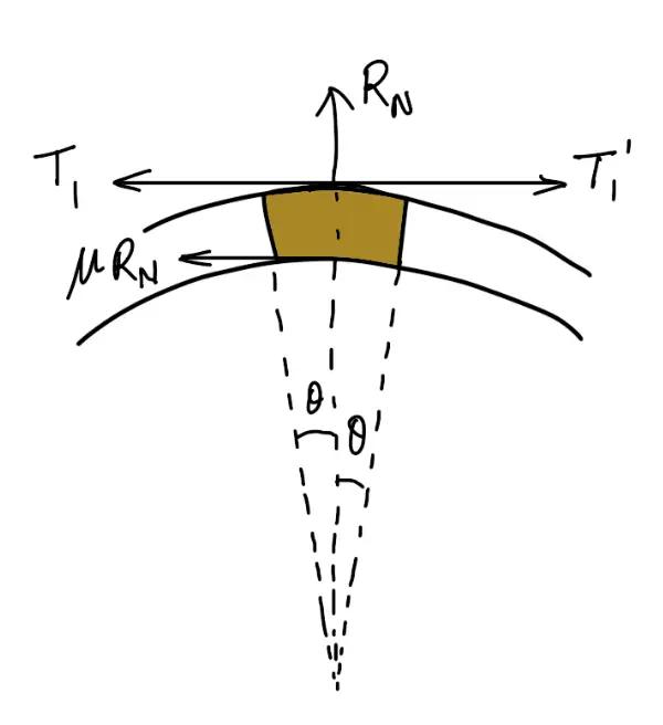
- Tension in the tight side (T1),
- Tension in the slack side (T1‘) or tension in the band between the first and second block,
- Normal reaction of the drum on the block (RN), and
- The force of friction (μ.RN).
Resolving the forces radially, we have
(T1 + T1‘) sin θ = RN
Resolving the forces tangentially, we have
(T1 – T1‘) cos θ = μ.RN
Let us divide the second equation with the first one, and we get
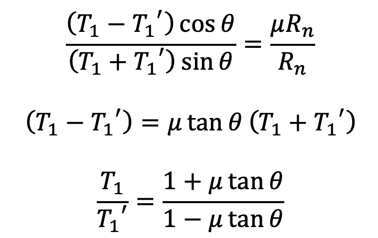
Similarly, it can be proved for each of the blocks that


Braking torque on the drum of effective radius re,
TB = (T1 –T2)re
(If Neglecting the thickness of the band)
TB = (T1 – T2) r
👉Important Note:
For the first block, the tension in the tight side is T1 and in the slack side is T1‘ and for the second block, the tension in the tight side is T1‘ and in the slack side is T2‘. Similarly, for the third block, the tension in the tight side is T2‘ and in the slack side is T3‘ and so on. For the last block, the tension in the tight side is Tn – 1, and in the slack side is T2.
How to Calculate the Force Required to Brake with Band and Block Brake?
Problem Statement: In the band and block brake shown in the following figure, the band is lined with 12 blocks each of which subtends an angle of 15° at the center of the rotating drum. The thickness of the blocks is 75 mm and the diameter of the drum is 850 mm. If, when the brake is inaction, the greatest and least tensions in the brake strap are T1 and T2, showing that

With the lever arrangement as shown in the following figure, find the least force required at C for the blocks to absorb 225 kW at 240 r.p.m. The coefficient of friction between the band and blocks is 0.4. (where μ is the coefficient of friction for the blocks.)
Answer:
Given Data
Number of blocks n = 12
Angle 2θ = 15°or θ= 7.5 °
Thickness of the block t = 75mm = 0.075m
Diameter of the Drum d = 850mm =0.85m
Power = 225kW = 225 × 103 W
Speed N = 240 r.p.m
Coefficient of friction μ = 0.4
Since OA > OB, therefore the force at C must act down- ward. Also, the drum rotates clockwise, therefore the end of the band attached to A will be slack with tension T2 (least tension) and the end of the band attached to B will be tight with tension T1 (greatest tension).
Consider one of the blocks (say the first block) as shown in the following figure.
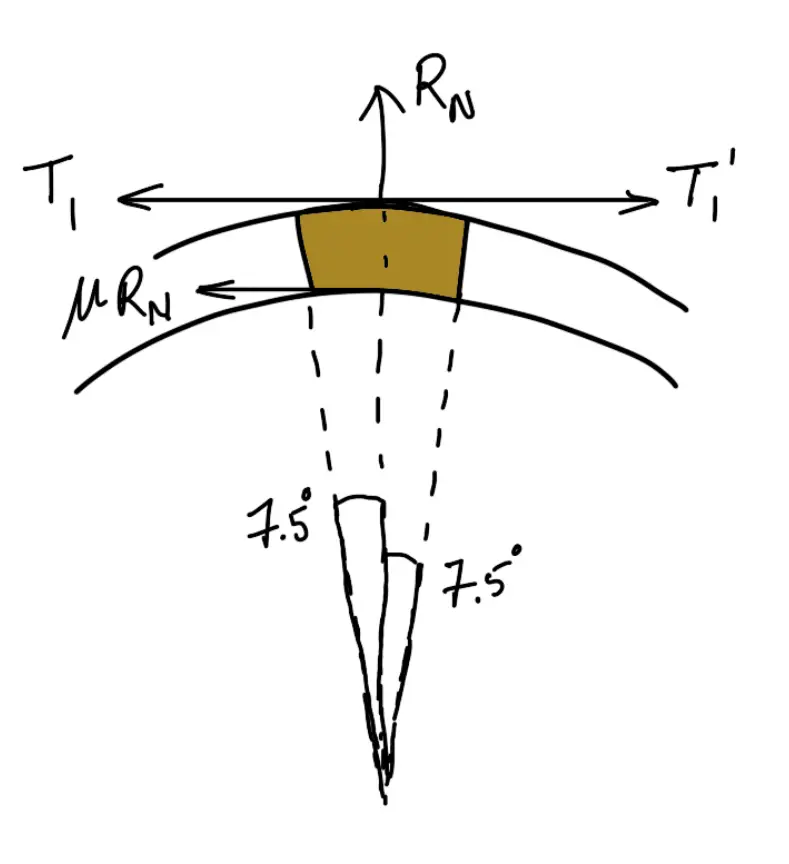
This is in equilibrium under the action of the following four forces:
- Tension in the tight side (T1),
- Tension in the slack side (T1‘) or tension in the band between the first and second block,
- Normal reaction of the drum on the block (RN), and
- The force of friction (μ.RN).
Resolving the forces radially, we have
(T1 + T1‘) sin 7.5∘ = RN
Resolving the forces tangentially, we have
(T1 – T1‘) cos 7.5∘ = μ.RN
Let us divide the second equation with the first one, and we get
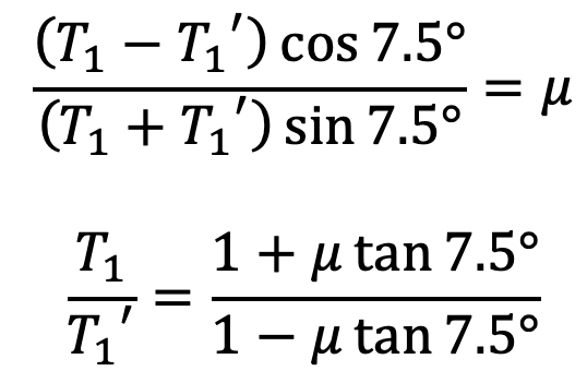
Similarly, for the other blocks, the ratio of tensions remains constant. Therefore for 12 blocks having greatest tension T1 and least tension T2 is

Least force required at C
Let P = Least force required at C.
We know the diameter of the band.
D = d + 2 t
D = 0.85 + 2 × 0.075
D = 1 m
Power Absorbed
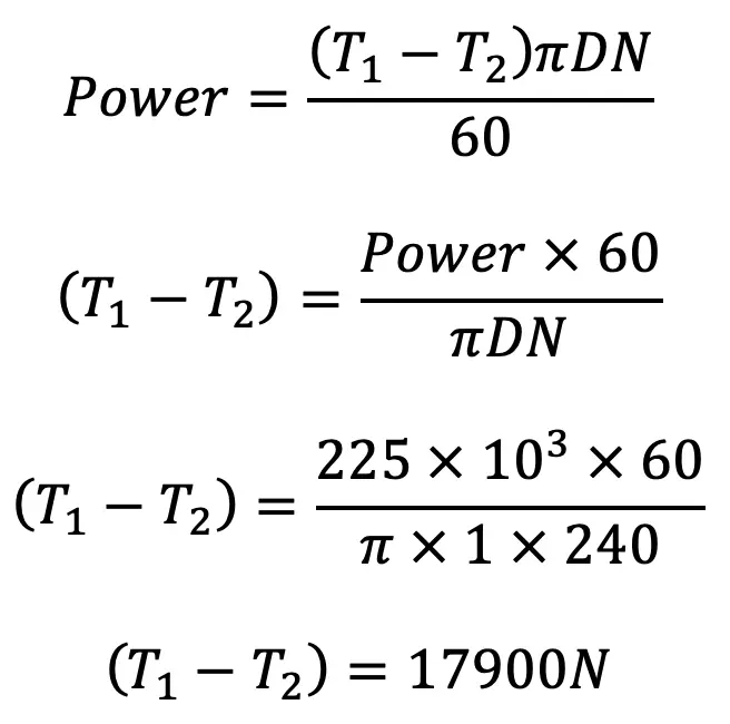
We have proved that
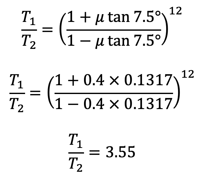
From the above two equations, we find that
T1 = 24920N
T2 = 7020N
Now taking moments about O, we have
P × 500 = T2 × 150 – T1 × 30
P × 500 = 7020 × 150 – 24920 × 30
P × 500 = 305400
P = 305400/500
P = 610.8N
The Least force required to Calculate the Force Required to Brake with Band and Block Brake is 610.8N.

Leave a Reply