Hydraulic machines are those that convert either hydraulic energy (energy possessed by water) into mechanical energy (which is further converted into electrical energy ) or mechanical energy into hydraulic energy. The hydraulic machines, which convert the hydraulic energy into mechanical energy, are called turbines while the hydraulic machines which convert the mechanical energy into hydraulic energy are called pumps. Axial flow Reaction Turbines are one of the types of turbines in which the water flows parallel to the axis of the rotation of the shaft. Kaplan Turbine is on type of Axial flow Turbine. Let us discuss more details such as Parts, construction, Working, Work done, and Efficiency of the Axial flow Reaction Turbine/ Kaplan Turbine.

Axial flow Reaction Turbine
If the water flows parallel to the axis of the rotation of the shaft, the turbine is known as an axial flow turbine. And suppose the head at the inlet of the turbine is the sum of pressure energy and kinetic energy. During water flow through the runner, a part of the pressure energy is converted into kinetic energy. In that case, the turbine is known as a reaction turbine.
For the axial flow reaction turbine, the shaft of the turbine is vertical. The lower end of the shaft is made larger which is known as ‘hub’ or ‘boss’. The vanes are fixed on the hub and hence hub acts as a runner for axial flow reaction turbine.
The following are the important type of axial flow reaction turbines :
- Propeller Turbine
- Kaplan Turbine
When the vanes are fixed to the hub and they are not adjustable, the turbine is known as propeller turbine. But if the vanes on the hub are adjustable, the turbine is known as a Kaplan Turbine. This turbine is named after the name of V Kaplan, an Austrian Engineer. This turbine is suitable where a large quantity of water at low head is available.

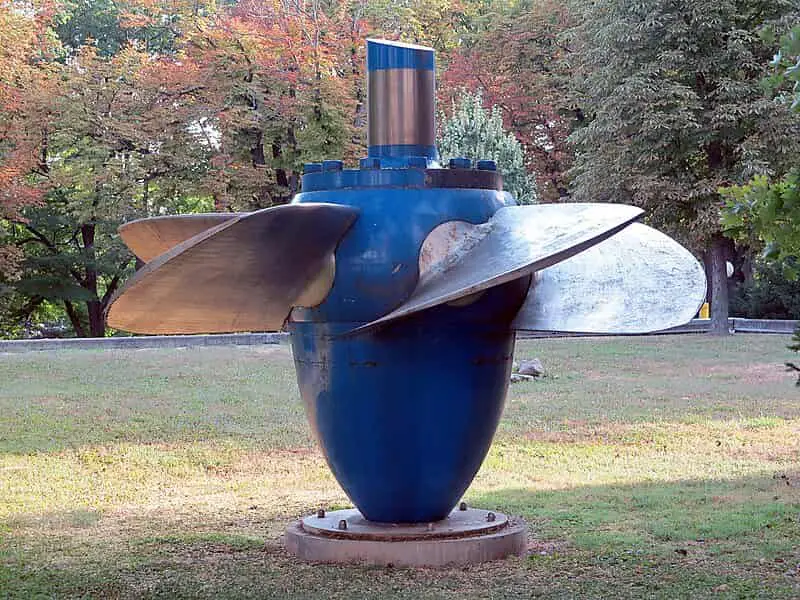
The above figure shows the runner of a Kaplan turbine, which consists of a hub fixed to the shaft. On the hub, the adjustable vanes are fixed as shown in the above figure.
The main parts of a Kaplan turbine are :
- Scroll casing
- Guide vanes mechanism
- Hub with vanes or runner of the turbine
- Draft tube
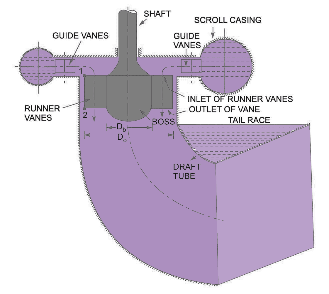
In the following figuire shows all main parts of a Kaplan turbine. The water from penstock enters the scroll casing and then moves to the guide vanes. From the guide vanes, the water turns through 90° and flows axially through the runner as shown in the following figure.

The discharge through the runner is obtained as

where
Do = Outer diameter of the runner
Db = Diameter of hub
Vf1 = Velocity of flow at inlet
The inlet and outlet velocity triangles are drawn at the extreme edge of therunner vane corresponding to the points 1 and 2 as shown in above figure.
Desgin Parameters for Kaplan Turbine
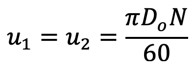
- The peripheral velocity at inlet and outlet are equal

- Velocity of flow at inlet and outlet are equal
Vf1 = Vf2 - Area of flow at inlet = Area of flow at outlet = π/4 (Do2 – Db2)
This is all about the Axial flow Reaction Turbine / Kaplan Turbine. Let us know what you think about this article in the comment section below.

Leave a Reply