A Mini Project on “Automatic Railway Gate Control System” submitted by Mohan K (from Alagappa Chettiar Government College Of Engineering And Technology karaikudi) to extrudesign.com.
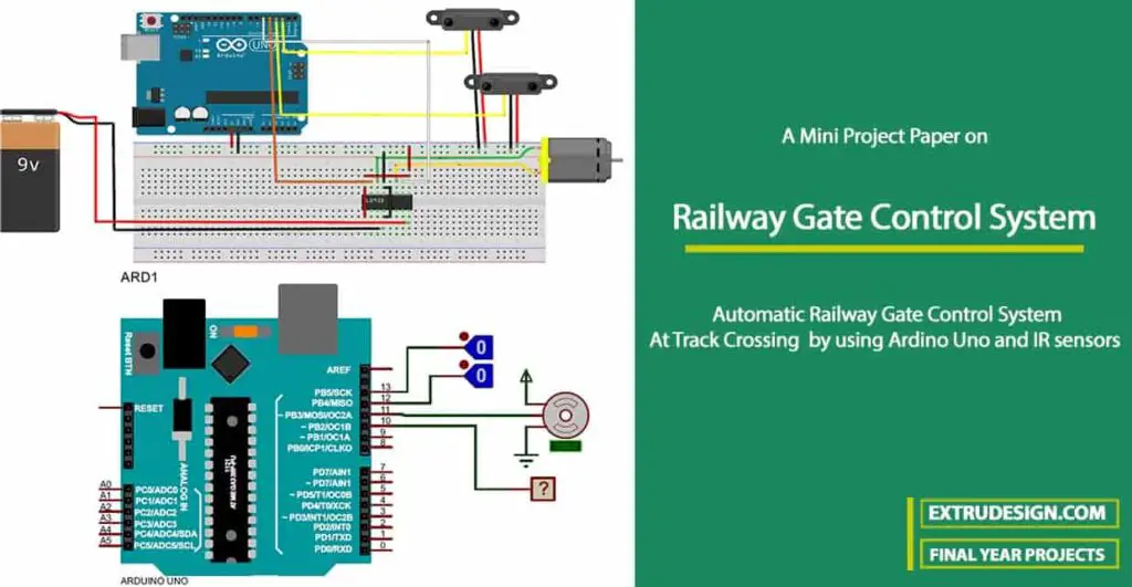
Abstract: Automatic Gate Control System At Track Crossing
The automatic gate opening/closing system is provided with the Reflection sensors placed at a distance of a few kilometers on both sides from the crossing road. These sensors give the train reaching and leaving status to the controller at the gate to which they are connected. The controller (AUDRINO) operates (open/close) the gate as per the received signal from the Reflection sensors.
Block Diagram
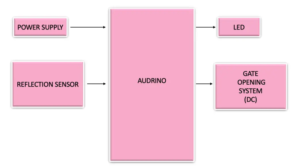
- The objective of this project is to provide signalling system for the railways to enter and leave the track.
- The automatic gate opening/closing system is provided with the Reflection sensors placed at a distance of few kilometers on the both sides from the crossing road.
- These sensors give the train reaching and leaving status to the controller at the gate to which they are connected.
- The controller operates (open/close) the gate as per the received signal from the Reflection sensors.
Hardware Components for Railway Gate Control System
- Audrino Uno
- DC Power supply (bridge rectifier)
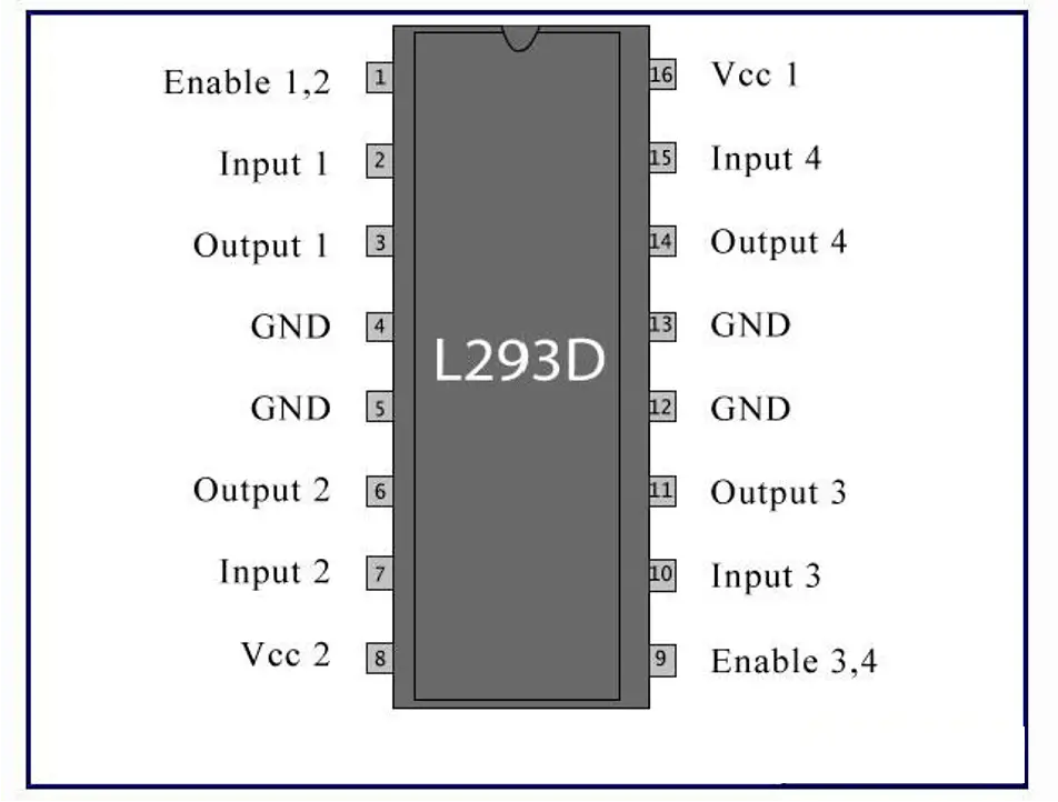
- 7812 voltage regulator (motor driver)
- IR sensor Pairs
- Servo Motor
- LEDs7. Jumper Wires
Audrino Uno R3
- The Arduino UNO is a widely used open-source microcontroller board based on the ATmega328P microcontroller and developed by Arduino.cc.
- The board is equipped with sets of digital and analog input/output (I/O) pins that may be interfaced to various expansion boards (shields) and other circuits. The board features 14 Digital pins and 6 Analog pins.
- It is programmable with the Arduino IDE(Integrated Development Environment) via a type B USB cable.
- It can be powered by a USB cable or by an external 9 volt battery, though it accepts voltages between 7 and 20 volts
DC Power supply

- The power supplies are designed to convert high voltage AC mains electricity to a suitable low voltage supply for electronics circuits and other devices.
- A power supply can by broken down into a series of blocks, each of which performs a particular function.
- A d.c power supply which maintains the output voltage constant irrespective of a.c mains fluctuations or load variations is known as “Regulated D.C Power Supply”
7812 Voltage Regulator (Motor Driver)
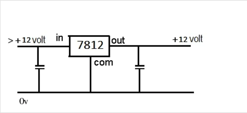
- 7812 Voltage regulator is a type of self-contained fixed linear voltage regulator integrated circuit. The IC belongs to ic 78xx voltage regulator family.
- The 7812 voltage regulator IC is ease-of-use and available in very low cost. The last two digits of 7812 indicates the output voltage that is 12 V
- The 7812 ic have 3 pins.
- The positive input is at pin 1.
- The Pin 2 is common between both input as well as output voltage.
- Pin 3 is a positive output.
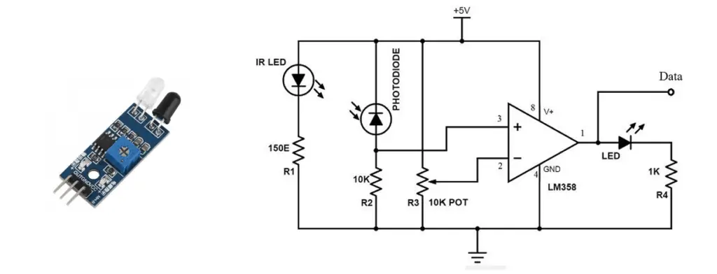
IR sensor Module and its components
- IR pair (IR LED and Photodiode)
- IC LM358
- Resistor 100, 10k, 330 ohm
- Variable resistor – 10k
- LED
Servo motor
•servomotor is a rotary actuator or linear actuator that allows for precise control of angular or linear position, velocity, and acceleration. It consists of a suitable motor coupled to a sensor for position feedback.• It also requires a relatively sophisticated controller, often a dedicated module designed specifically for use with servo motors. •Servomotors are not a specific class motor although the term servomotor is often used to refer to a motor suitable for use in a closed-loop control system.
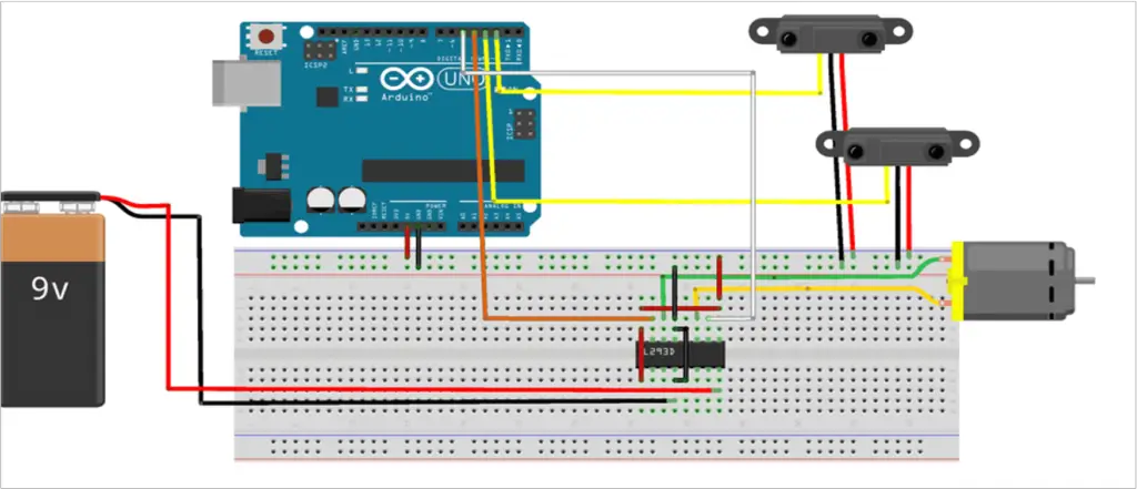
Circuit diagram of the Automatic Railway Gate Control System
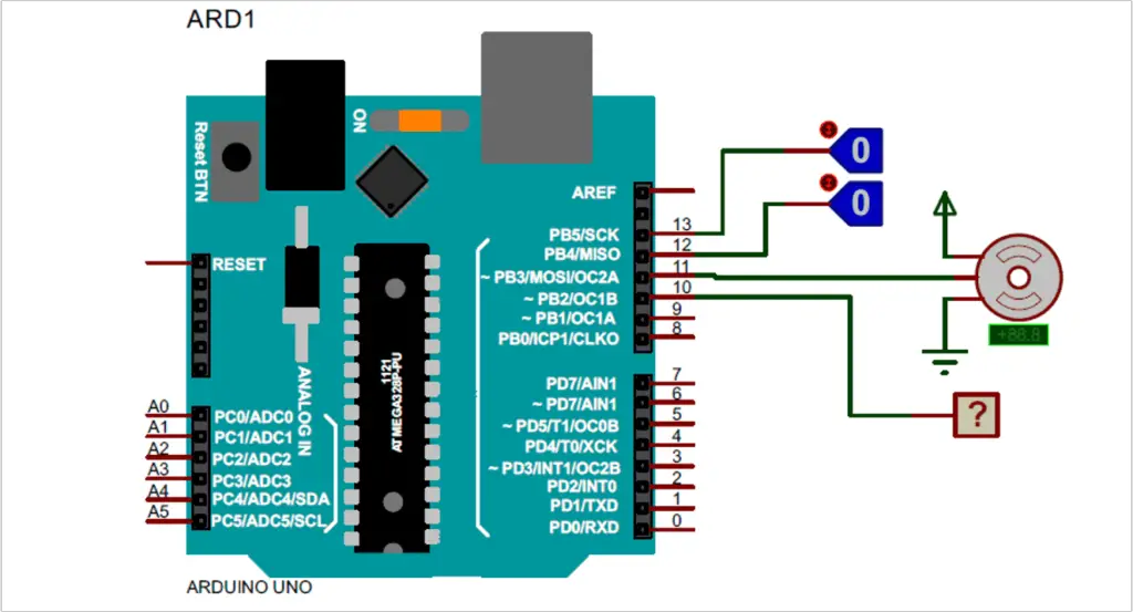
Simulation Diagram of the Automatic Railway Gate Control System
Program code for Automatic Railway Gate Control System
#include <Arduino.h>
#include <avr/io.h>
#include <Servo.h>

#ifndef SensorConfig
#define SensorConfig
#define Sensor1 13
#define Sensor2 12
#endif

#ifndef ServoConfig
#define ServoConfig
#define ServoMotor  11
#define GateOpen    0
#define GateClose   90
#endif

#ifndef OutputConfig
#define OutputConfig
#define Alarm      10
#define AlarmDelay 1000 //milliseconds
#endif

unsigned char BlockCount = 0;
unsigned long int AlarmTimer;
bool ISSensor1Sensed, ISSensor2Sensed, ISAlarmActivated;

Servo gate;

void setup()
{
  Serial.begin(9600);
  gate.attach(ServoMotor);
  gate.write(GateOpen);

  pinMode(Sensor1, INPUT);
  pinMode(Sensor2, INPUT);

  pinMode(Alarm, OUTPUT);
  digitalWrite(Alarm, LOW);
}
void loop()
{
  if(!BlockCount && !digitalRead(Sensor1) && !ISSensor1Sensed && !ISSensor2Sensed)
  {
    ISSensor1Sensed = true;
    while(!digitalRead(Sensor1));
    BlockCount++; Serial.println(BlockCount);
  }
  else if(!digitalRead(Sensor1) && ISSensor1Sensed)
  {
    while(!digitalRead(Sensor1));
    BlockCount++; Serial.println(BlockCount);
  }
  else if(!digitalRead(Sensor2) && ISSensor1Sensed)
  {
    while(!digitalRead(Sensor2));
    BlockCount--; Serial.println(BlockCount);
  }

  if(!BlockCount && !digitalRead(Sensor2) && !ISSensor1Sensed && !ISSensor2Sensed)
  {
    ISSensor2Sensed = true;
    while(!digitalRead(Sensor2));
    BlockCount++;
  }
else if(!digitalRead(Sensor2) && ISSensor2Sensed)
  {
    while(!digitalRead(Sensor2));
    BlockCount++;
  }
  else if(!digitalRead(Sensor1) && ISSensor2Sensed)
  {
    while(!digitalRead(Sensor1));
    BlockCount--;
  }

  if(BlockCount && !ISAlarmActivated)
  {
    ISAlarmActivated = true;
    digitalWrite(Alarm, HIGH);
    AlarmTimer = millis() + AlarmDelay;
  }

 else if(BlockCount && AlarmTimer < millis())
  {
    digitalWrite(Alarm, LOW);
    gate.write(GateClose);
  }
  else if(BlockCount == 0 && ISAlarmActivated)
  {
    ISAlarmActivated = false;
    ISSensor1Sensed = false;
    ISSensor2Sensed = false;
    BlockCount = false;
    gate.write(GateOpen);
  }
}
Conclusion
The project work has been completed successfully. The project hardware functions satisfactorily as per the design. The project work was developed after conducting a number of experiments before finalizing the design work, this reduced the bottlenecks and we did not face much difficulty in the final integration process. In general, the entire development of the project work was educative and we could gain a lot of experience by way of doing the project practically. We could understand the practical constraints of developing such systems about which we have studied by way of lectures in the theory classes.
Credit: This Mini Project “Automatic Railway Gate Control System” was completed by Anantha Kumar M, Balaguruvenkatesh S, Mohan K, and Jayakumar T under the guidance of Prof.M.L.Ramamoorthy from the department of Electrical And Electronics Engineering of Alagappa Chettiar Government College Of Engineering And Technology karaikudi.
Courtesy Note: All the content, images, references are used for academic education purposes in the fulfillment of the respective degree by the student. The ownership of the materials, images, presented in this project paper is retained to its original creator. kindly note that this has to be treated kindly.

Leave a Reply