In mechanical engineering System of limits or Limit System is a concept of controlling the sizes of machine elements while manufacturing each component. Because taking exact dimensions is an ideal condition but in practical(Manufacturing/Measuring) methods, it is not possible. So limit system enables how much amount of deviation is acceptable.
How do we apply the limit system in the design of the machine elements?
When one part is matting with another one, first of all, the fit between the two parts must be determined. [Learn more about Types of Fits]. To determine the fit, we must take one component as the constant member and the second component will have the deviations according to the type of fit chosen.
By making a constant member we can classify them as hole basis system and shaft basis system. these are the two bases of the limit system. In the hole basis system Hole values are constant and the deviations will be considered in the shaft dimensions. In the Shaft basis system the shaft dimensions are constant and the deviation will be considered in the hole dimensions.
[Learn more about Hole basis system and shaft basis system]
Let’s back to the subject, so what are the important nomenclature used in the limit system?
Important Terms Used in Limit System
- Nominal size
- Basic size
- Actual size
- Limits of sizes
- Tolerance
- Allowance
- Tolerance zone
- Zero line
- Upper deviation
- Lower deviation
- Actual deviation
- Mean deviation
- Fundamental deviation
These are the important terms used in the limit system. Let’s see what are the definitions of all the above-listed terms in the Limit System?
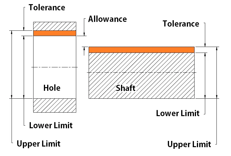
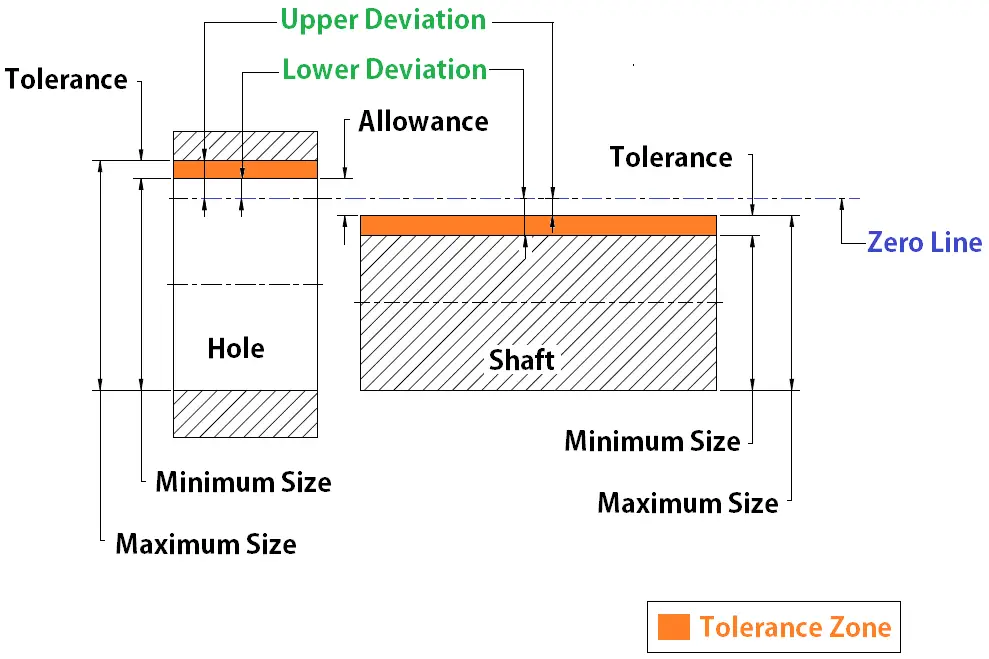
Before going getting to know about the definitions we need to understand the following schematic diagram which will help us to understand the definitions in a more clever manner.

The term shaft is meant for any external dimension of the part whereas the hole represents the internal dimension of the part.
Nominal size
The exact size of the component is mentioned in the drawing for the ideal condition. ( For convenience purpose only).
Example: A 30mm shaft. Here 30mm is the Nominal size. where we use a 30mm hole for this shaft. but further, we apply limits accordingly with the type of fits
Basic Size
This basic size and nominal size often the same. This basic size is the dimensions where we apply tolerances.
Example: 30.000±0.015 where the 30.00 is the basic size.
Actual Size
This is the actual dimension of the part taken by a measuring instrument. This actual dimension should not exceed the tolerance limits mentioned in the basic size.
Example: The size of the Shaft measured with the vernier calliper is 30.010 (This is an actual dimension of the shaft)
Limits of Sizes
The extreme possible deviation is called the limit of the size. there are two extreme possible limits of sizes. they are the maximum limit(Upper Limit), The Minimum Limit(Lower limit).
Example: A shaft dimensioned is mentioned 30.000±0.015 then 30.015 is the maximum limit(Upper Limit), 29.985 is the minimum Limit(Lower Limit)
Allowance
The difference between the basic size of the hole and shaft is known as the allowance(From the above figure we can define it as the difference between the lower limit of the hole and the Upper limit of the shaft ). It is positive when the shaft size is smaller than the hole size. It is negative when the shaft size is larger than the hole size.
Example:
Hole = 29.990/29.980, Shaft = 30.000/29.970
Allowance = 29.980-30.000 = -0.020 (Interference of material occurred)
Tolerance
The difference between the Upper limit and the lower limit of a hole or a shaft is known as Tolerance. It can also be said as the maximum permissible deviation with the basic size is known as the Tolerance.
Tolerance can be a unilateral system of tolerance or a bilateral system of tolerance.

Example:
Tolerance= 30.030-30.000 = 0.030 (Unilateral System)
Tolerance = 30.015-29.985 = 0.030 (Bilateral System)
Tolerance Zone
The zone between the Upper limit and the lower limit is known as the tolerance zone.

Zero Line
The imaginary straight line corresponding to the basic size of the shaft or hole, which is used to measure the deviations.
Upper Deviation
The difference between the basic size and the Maximum size is known as the upper deviation.
Example: Shaft = 30.000±0.015
Upper Deviation = 30.015-30.000 = 0.015
Lower deviation
The difference between the basic size and the Minimum size is known as the Lower deviation.
Example: Shaft = 30.000±0.015
Lower Deviation = 30.000-29.985 = 0.015
Actual deviation
The difference between the basic size and the actual size of the part after manufactured. (Measured with an instrument) is known as the actual deviation.
Example: Shaft = 30.000±0.015
Vernier calliper measurement of the shaft (after manufactured )= 30.010
Actual Deviation = Basic size(30.000)- Component actual size(30.010) = 0.010
Mean deviation
(Upper Deviation +Lower Deviation)/2 = Mean deviation
Fundamental Deviation
The fundamental deviation is the form of allowance. In shafts, it is said to be an upper deviation. In holes, it is said to be a lower deviation.
Example:
Hole = 29.990/29.980, Shaft = 30.000/29.970
Allowance = 29.980-30.000 = -0.020 (Interference of material occurred)
Fundamental Deviation of hole = 0.020
Fundamental deviation of shaft = 0
Conclusion
The important terms in the limit system play a very crucial role in machine design. The type of fits and the basic system are the next important topics.

Leave a Reply