Alloy steels are developed to overcome the Plain carbon steel limitations and deficiencies. Alloy steels, in general, cost more than plain-carbon steels, but for many applications, they are the only materials that can be used to meet engineering requirements. Let us discuss the alloy steels in detail.
As we mentioned that alloy steels are developed in order to overcome the Plain carbon steel limitations. Following are some of the Plain carbon steel limitations.
Plain-carbon steels Limitations
Plain-carbon steels can be used successfully if the strength and other engineering requirements are not too severe. These steels are relatively low in cost but have some limitations, which include the following:
- Plain-carbon steels cannot be strengthened beyond about 100,000 psi (690 MPa) without a substantial loss in ductility and impact resistance.
- Large-section thicknesses of plain-carbon steels cannot be produced with a martensitic structure throughout, that is, they are not deep-hardenable.
- Plain-carbon steels have low corrosion and oxidation resistance.
- Medium-carbon plain-carbon steels must be quenched rapidly to obtain a fully martensitic structure. Rapid quenching leads to possible distortion and cracking of the heat-treated part.
- Plain-carbon steels have poor impact resistance at low temperatures
To overcome the deficiencies of plain-carbon steels, alloy steels have been developed that contain alloying elements to improve their properties.
Alloy Steels
The principal alloying elements added to make alloy steels are
- Manganese
- Nickel
- Chromium
- Molybdenum
- Tungsten
- Other elements that are sometimes added are vanadium, cobalt, boron, copper, aluminum, lead, titanium, and columbium (niobium).
Classification of Alloy Steels
Alloy steels may contain up to 50% of alloying elements and still be considered alloy steels. In this article, low-alloy steels containing from about 1% to 4% of alloying elements will be considered alloy steels. These steels are mainly automotive and construction type steels and are commonly referred to simply as alloy steels.
Alloy steels in the United States are usually designated by the four-digit AISI-SAE system.
The first two digits indicate the principal alloying element or groups of elements in the steel, and the last two digits indicate the hundredths of a percent of the carbon in the steel.
The following table 1 lists the nominal compositions of the principal types of standard alloy steels.
Table 1: Principal types of standard alloy steels
| 13xx | Manganese 1.75 |
| 40xx | Molybdenum 0.20 or 0.25; or molybdenum 0.25 and sulfur 0.042 |
| 41xx | Chromium 0.50, 0.80, or 0.95, molybdenum 0.12, 0.20, or 0.30 |
| 43xx | Nickel 1.83, chromium 0.50 or 0.80, molybdenum 0.25 |
| 44xx | Molybdenum 0.53 |
| 46xx | Nickel 0.85 or 1.83, molybdenum 0.20 or 0.25 |
| 47xx | Nickel 1.05, chromium 0.45, molybdenum 0.20 or 0.35 |
| 48xx | Nickel 3.50, molybdenum 0.25 |
| 50xx | Chromium 0.40 |
| 51xx | Chromium 0.80, 0.88, 0.93, 0.95, or 1.00 |
| 51xxx | Chromium 1.03 |
| 52xxx | Chromium 1.45 |
| 61xx | Chromium 0.60 or 0.95, vanadium 0.13 or min 0.15 |
| 86xx | Nickel 0.55, chromium 0.50, molybdenum 0.20 |
| 87xx | Nickel 0.55, chromium 0.50, molybdenum 0.25 |
| 88xx | Nickel 0.55, chromium 0.50, molybdenum 0.35 |
| 92xx | Silicon 2.00; or silicon 1.40 and chromium 0.70 |
| 50Bxx | Chromium 0.28 or 0.50 |
| 51Bxx | Chromium 0.80 |
| 81Bxx | Nickel 0.30, chromium 0.45, molybdenum 0.12 |
| 94Bxx | Nickel 0.45, chromium 0.40, molybdenum 0.12 |
Distribution of Alloying Elements in Alloy Steels
The way in which alloy elements distribute themselves in carbon steels depends primarily on the compound and carbide forming tendencies of each element.
Following table 2 summarizes the approximate distribution of most of the alloying elements present in alloy steels.
Table 2: Approximate distribution of alloying elements in alloy steels
| Element | Dissolved in Ferrite | Combined in Carbide | Combined as Carbide | Compound | Elemental | |
| Nickel | Ni | Ni3Al | ||||
| Silicon | Si | SiO2 ·MxOy | ||||
| Manganese | Mn | ⟷ | Mn | (Fe, Mn)3C | MnS; MnO·SiO2 | |
| Chromium | Cr | ⟷ | Cr | (Fe, Cr3)C | ||
| Cr7C3 | ||||||
| Cr23C6 | ||||||
| Molybdenum | Mo | ⟷ | Mo | Mo2C | ||
| Tungsten | W | ⟷ | W | W2C | ||
| Vanadium | V | ⟷ | V | V4C3 | ||
| Titanium | Ti | ⟷ | Ti | TiC | ||
| Columbium† | Cb | ⟷ | Cb | CbC | ||
| Aluminum | Al | Al2O3; AIN | ||||
| Copper | Cu(small amount) | |||||
| Lead | Pb |
Note: The arrows in the above table indicate the relative tendencies of the elements listed to dissolve in the ferrite or combine in carbides.
- Nickel dissolves in the α ferrite of the steel since it has less tendency to form carbides than iron.
- Silicon combines to a limited extent with the oxygen in the steel to form nonmetallic inclusions but otherwise dissolves in the ferrite.
- Most of the manganese added to carbon steels dissolves in the ferrite. Some of the manganese, however, will form carbides but will usually enter the cementite as (Fe, Mn)3C.
- Chromium, which has a somewhat stronger carbide-forming tendency than iron, partitions between the ferrite and carbide phases. The distribution of chromium depends on the amount of carbon present and on whether other stronger carbide forming elements such as titanium and columbium are absent.
- Tungsten and molybdenum combine with carbon to form carbides if there is sufficient carbon present and if other stronger carbide-forming elements such as titanium and columbium are absent.
- Vanadium, titanium, and columbium are strong carbide-forming elements and are found in steels mainly as carbides.
- Aluminum combines with oxygen and nitrogen to form the compounds Al2O3 and AlN, respectively.
Effects of Alloying Elements on the Eutectoid Temperature of Steels
The various alloying elements cause the eutectoid temperature of the Fe–Fe3C phase diagram to be raised or lowered.
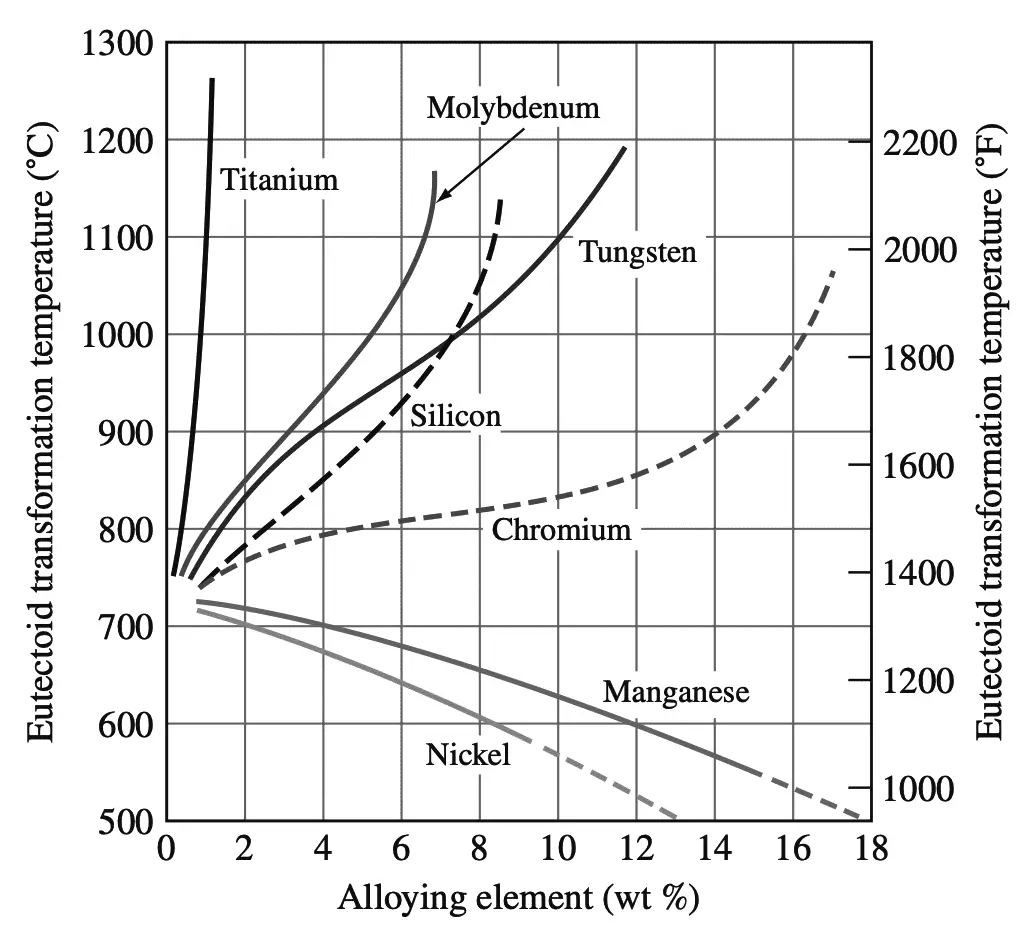
Manganese and nickel both lower the eutectoid temperature and act as austenite-stabilizing elements enlarging the austenitic region of the Fe–Fe3C phase diagram.
In some steels with sufficient amounts of nickel or manganese, the austenitic structure may be obtained at room temperature. The carbide-forming elements such as tungsten, molybdenum, and titanium raise the eutectoid temperature of the Fe–Fe3C phase diagram to higher values and reduce the austenitic phase field. These elements are called ferrite-stabilizing elements.
Read more about the effect of these alloy elements on the steel
Hardenability of Steel
The hardenability of steel is defined as that property that determines the depth and distribution of hardness induced by quenching from the austenitic condition. The hardenability of steel depends primarily on
(1) the composition of the steel,
(2) the austenitic grain size,
(3) the structure of the steel before quenching.
Hardenability should not be confused with the hardness of steel, which is its resistance to plastic
deformation, usually by indentation.
In industry, hardenability is most commonly measured by the Jominy hardenability test. In the Jominy end-quench test, the specimen consists of a cylindrical bar with a 1 in. diameter and 4 in. length and with a 1/16in. the flange at one end.
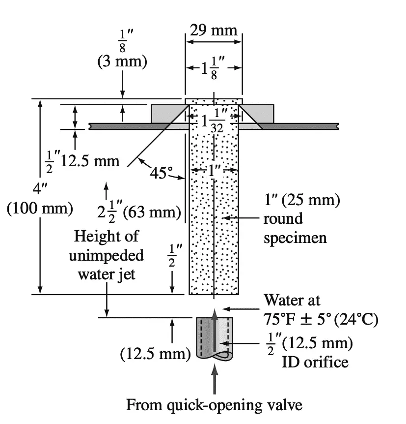
Since the prior structure has a strong effect on hardenability, the specimen is usually normalized before testing. In the Jominy test, after the sample has been austenitized, it is placed in a fixture, as shown in the below figure, and a jet of water is quickly splashed at one end of the specimen.
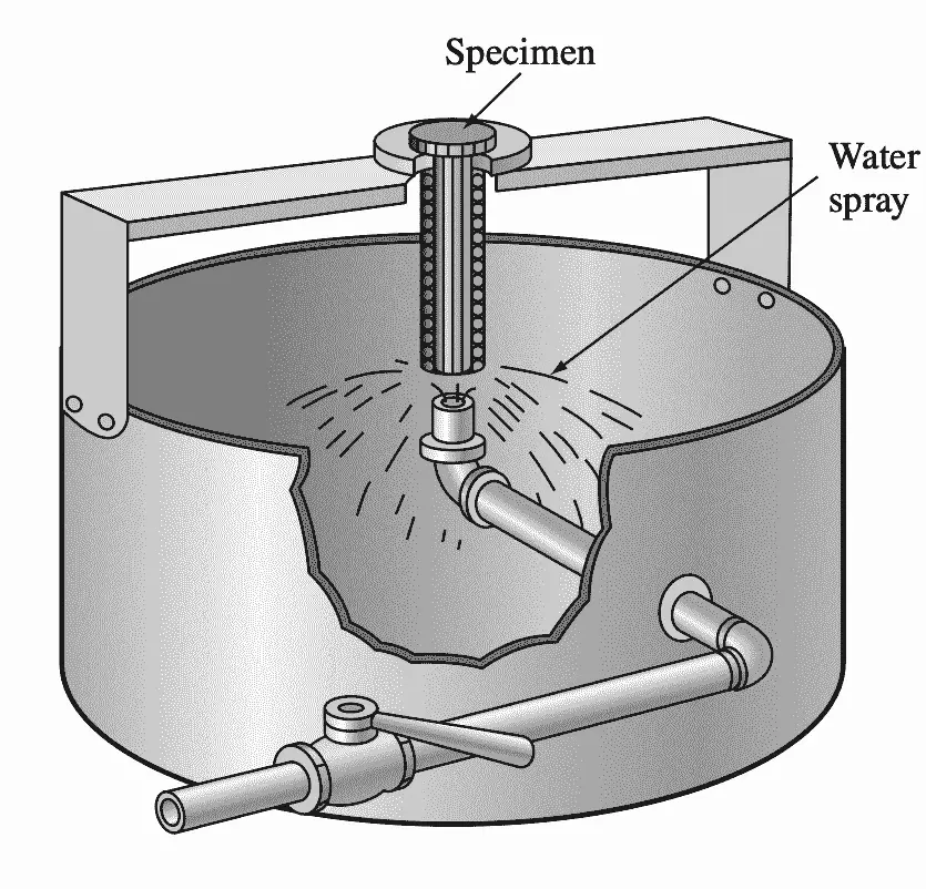
After cooling, two parallel flat surfaces are ground on the opposite sides of the test bar, and Rockwell C hardness measurements are made along these surfaces up to 2.5 in. from the quenched end.
The following graph 2 shows a hardenability plot of Rockwell C hardness versus distance from the quenched end for a 1080 eutectoid plain-carbon steel.
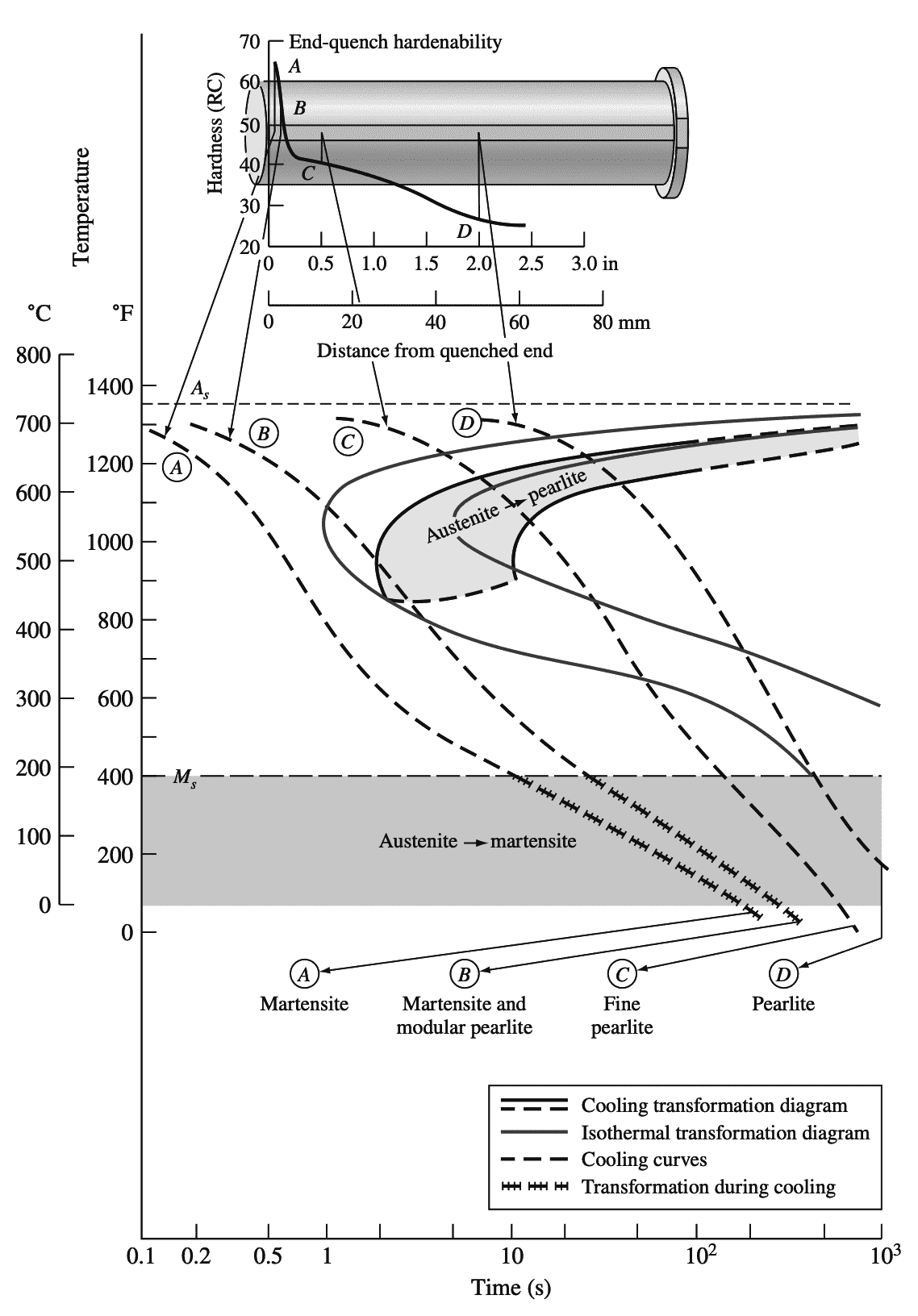
This steel has relatively low hardenability since its hardness decreases from a value of RC = 65 at the quenched end of the Jominy bar to RC = 50 at just 3/16in. from the quenched end. Thus, thick sections of this steel cannot be made fully martensitic by quenching.
The above graph 2 correlates the end-quench hardenability data with the continuous transformation diagram for the 1080 steel and indicates the microstructural changes that take place along the bar at four distances A, B, C, and D from the quenched end.
Hardenability curves for some 0.40% C alloy steels are shown in below graph 3.
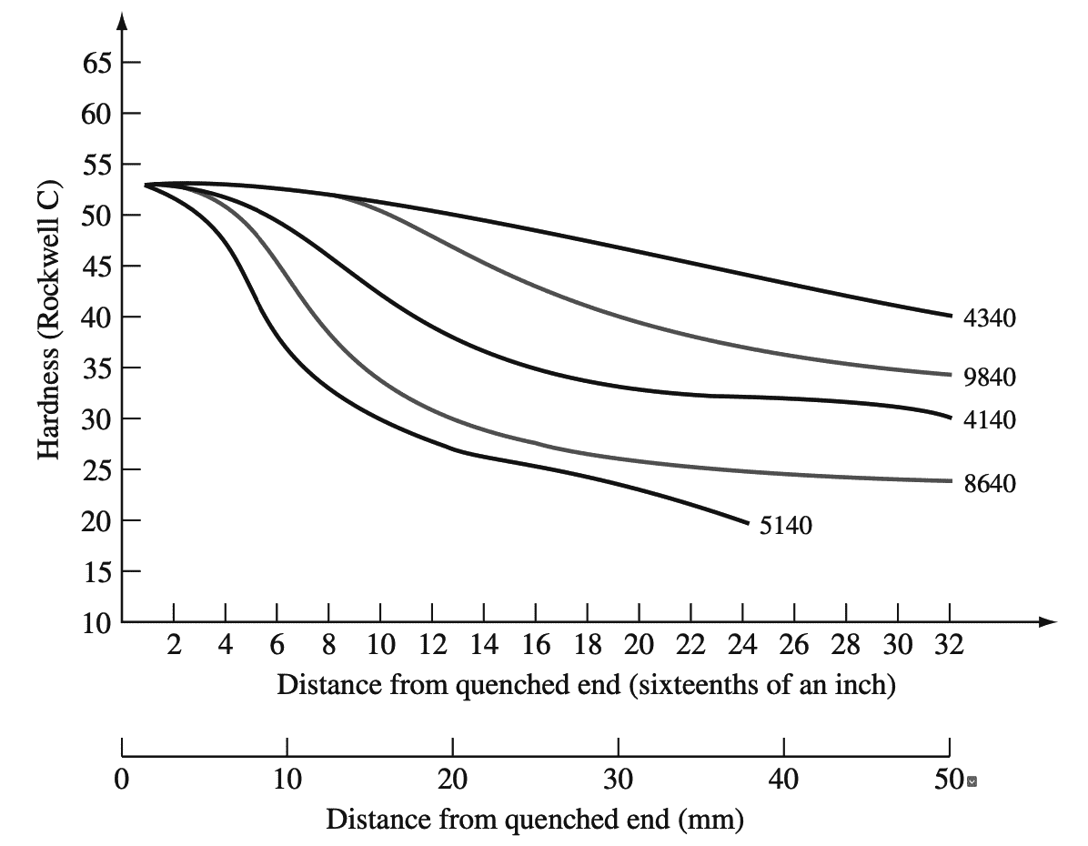
The 4340 alloy steel has exceptionally high hardenability and can be quenched to a hardness of RC = 40 at 2 in. from the quenched end of a Jominy bar. Alloy steels thus are able to be quenched at a slower rate and still maintain relatively high hardness values.
Alloy steels such as the 4340 steel are highly hardenable because, upon cooling from the austenitic region, the decomposition of austenite to ferrite and bainite is delayed and the decomposition of austenite to martensite can be accomplished at slower rates. This delay of the austenite to ferrite plus bainite decomposition is quantitatively shown on the continuous-cooling transformation diagram shown below in graph 4.
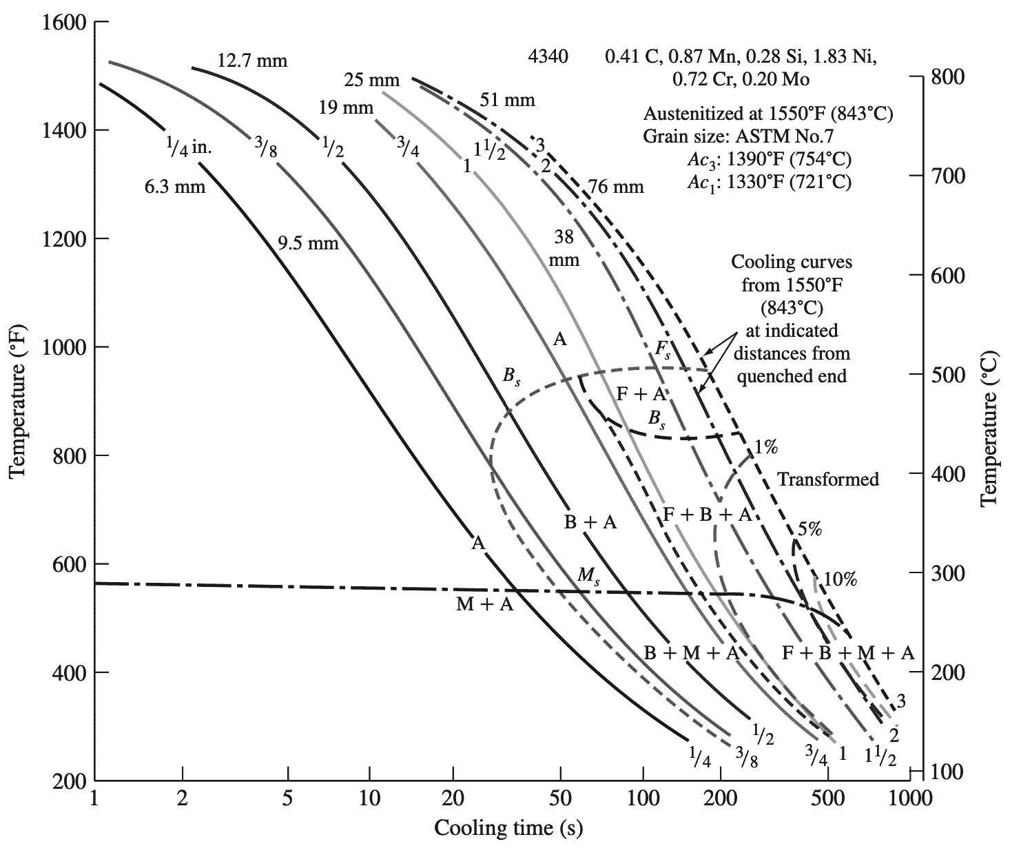
A = austenite,
F = ferrite,
B = bainite,
M = martensite.
For most carbon and low-alloy steels, a standard quench produces at the same cross-section position common cooling rates along long round steel bars of the same diameter. However, the cooling rates differ
(1) for different bar diameters,
(2) for different positions in the cross-sections of the bars,
(3) for different quenching media.
The following graph 4 shows bar diameter versus cooling rate curves for different crosssection locations within steel bars using quenches of agitated water in agitated oil.
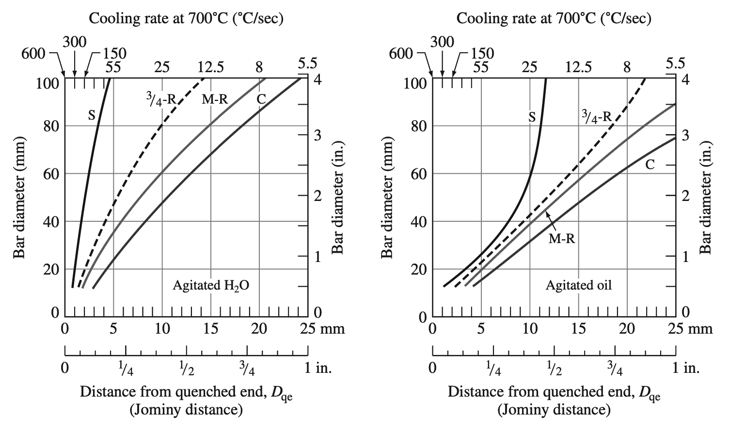
Top abscissa, cooling rates at 700°C; bottom abscissa, equivalent positions on an end quenched test bar.
(C = center, M-R = mid radius, S = surface, dashed line = approximate curve for 3/4 -radius positions on the cross-section of bars.)
These plots can be used to determine the cooling rate and the associated distance from the quenched end of a standard quenched Jominy bar for a selected bar diameter at a particular cross-section location in the bar using a specific quenching medium. These cooling rates and their associated distances from the end of Jominy quenched bars can be used with Jominy plots of surface hardness versus distance from the quenched end for specific steels to determine the hardness of particular steel at a specific location in the cross-section of the steel bar in question.
An Example Problem discussed below shows how the plots of the above graphs can be used to predict the hardness of a steel bar of a given diameter at a specific cross-section location quenched in a given medium. It should be pointed out that the Jominy hardness versus distance from the quenched-end plots are usually plotted as bands of data rather than as lines so that hardnesses obtained from the line curves are actually values in the center of a range of values.
Example Problem to Predict Rockwell C (RC) hardness of a bar
An austenitized 40 mm diameter 5140 alloy steel bar is quenched in agitated oil. Predict what the Rockwell C (RC) hardness of this bar will be at (a) its surface and (b) its center.
Answer:
a. Surface of the bar
The cooling rate at the surface of the 40 mm steel bar quenched in agitated oil is found from part (right) of graph 5 to be comparable to the cooling rate at 8 mm from the end of a standard quenched Jominy bar. Using the above graph 3 at 8 mm from the quenched end of the Jominy bar and the curve for the 5140 steel indicates that the hardness of the bar should be about 32 RC.
b. Center of the bar
The cooling rate at the center of the 40 mm diameter bar quenched in oil is found from part (right) of graph 5 to be associated with 13 mm from the end of a quenched Jominy bar. The corresponding hardness for this distance from the end of a quenched Jominy bar for the 5140 alloys is found by using the above graph 3 to be about 26 RC.
Typical Mechanical Properties and Applications for Low-Alloy Steels
Following table 3 lists some typical tensile mechanical properties and applications for some commonly used low-alloy steels.
Table 3: Typical mechanical properties and applications of low-alloy steels
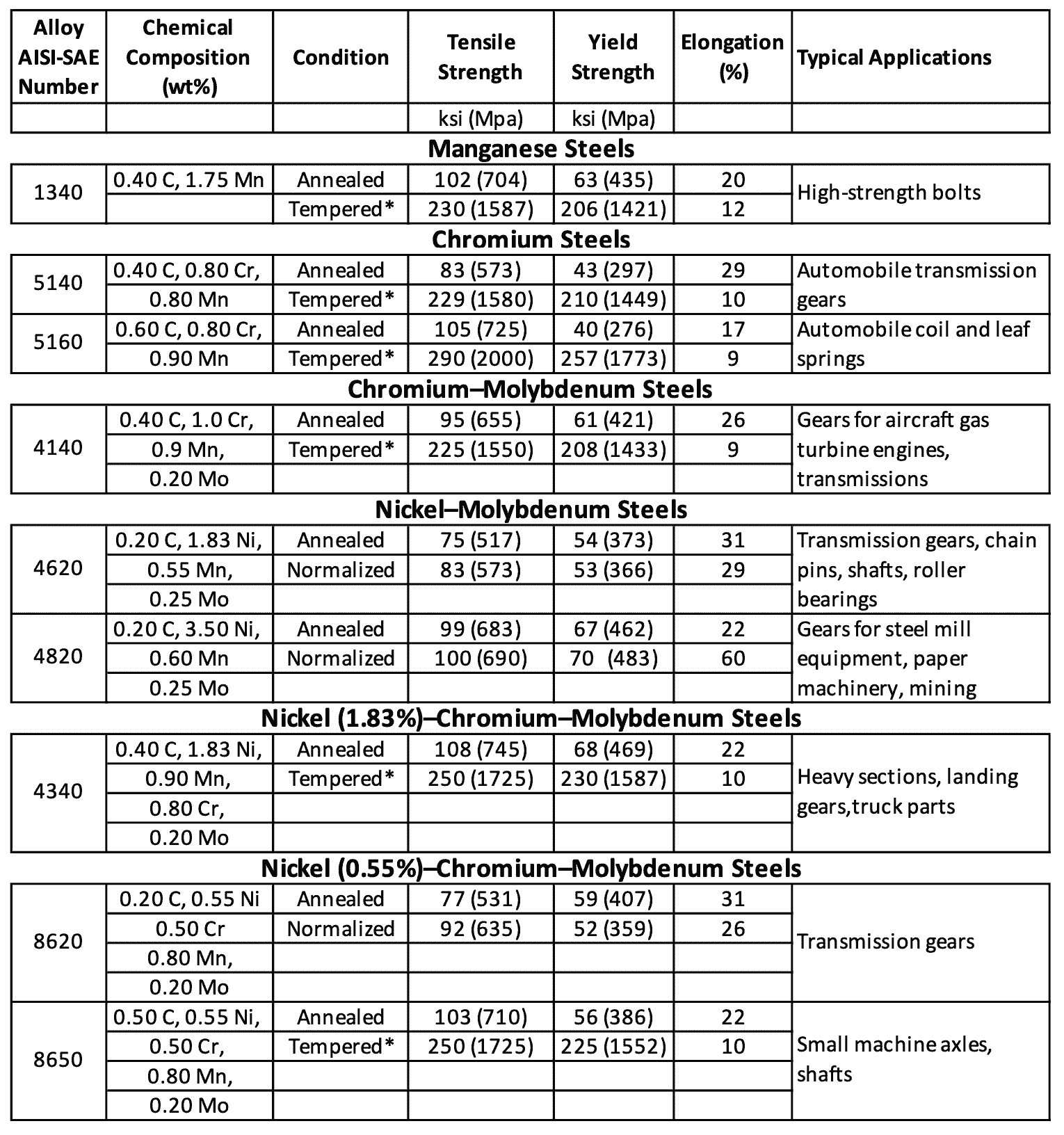
- For some strength levels, low-alloy steels have better combinations of strength, toughness, and ductility than plain-carbon steels.
- However, low-alloy steels cost more and so are used only when necessary.
- Low-alloy steels are used to a great extent in the manufacture of automobiles and trucks for parts that require superior strength and toughness properties that cannot be obtained from plain carbon steels.
- Some typical applications for low-alloy steels in automobiles are shafts, axles, gears, and springs.
- Low-alloy steels containing about 0.2% C are commonly carburized or surface heat-treated to produce a hard, wear-resistant surface while maintaining a tough inner core.

Leave a Reply