Torsional Rigidity is simply the resistance to the angular twist of any shaft or beam. But how it is different from Lateral Rigidity? Let us discuss Torsional Rigidity and Lateral Rigidity in detail to understand the differences.

In the previous articles, we have been discussing how to design a shaft if it is subjected to different loads such as Twisting moment, Bending moment, Fluctuating load, and axial load. This calculation procedure is completely based on the strength of the material factors such as the permissible tensile, compression, crushing, and shear stress.
There is another aspect of design shafts that is based on the rigidity of the material. That is where Torsional rigidity and Lateral rigidity come into play.
Torsional Rigidity
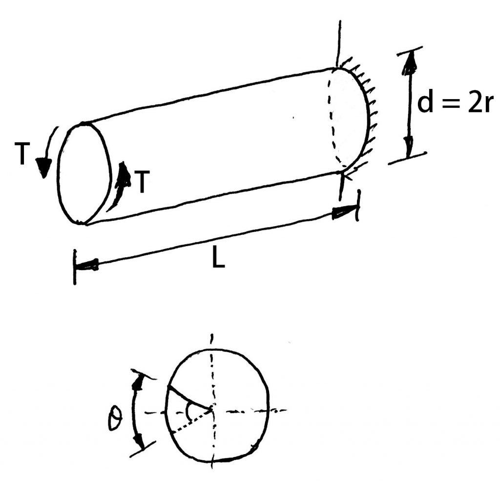
Torsional Rigidity is the resistance to the angular twist of the shaft along its rotational axis. The unit for the torsional rigidity is will be measured with the modulus of rigidity or shear modulus.
Torsional Rigidity is an important factor to consider while the shaft is subjected to the Twisting moments.
The torsional rigidity is important in the case of a camshaft of an Internal Combustion engine where the timing of the valves would be affected. The permissible amount of twist should not exceed 0.25° per meter length of such shafts.
For line shafts or transmission shafts, deflections 2.5 to 3 degrees per meter length may be used as a limiting value.
The widely used deflection for the shafts is limited to 1 degree in a length equal to twenty times the diameter of the shaft.
We know the Torsion Equation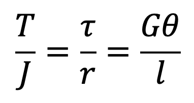
Let us consider the following portion of the equation in order to determine the torsional rigidity
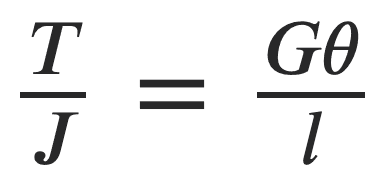
Where
θ = Torsional deflection or angle of twist in radians
T = Twisting moment or torque on the shaft
J = Polar moment of inertia of the cross-sectional area about the axis of rotation
G = Modulus of rigidity for the shaft material
L = Length of the shaft
If we rearrange as follows, we can get the Torsional Rigidity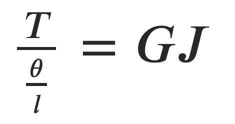
GJ will represent the Torsional Rigidity, which is the torque transmitted by the shaft for a unit angular twist in the unit of shaft length.
Torsional Stiffness formula for shaft
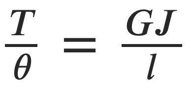
Torsional Stiffness of the shaft will be the torque transmitted by the shaft per unit angular twist in the shaft. Which will depend on the modulus of rigidity of the shaft material, cross-sectional shape of the shaft, and length of the shaft.
Torsional Deflection Formula
From this Torsiona equation, we can obtain the torsional deflection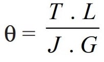
The Polar moment of inertia of the cross-sectional area about the axis of rotation for solid shafts is given below
The Polar moment of inertia of the cross-sectional area about the axis of rotation for hallow shafts is given below

Lateral Rigidity
Similarly, Lateral Rigidity is the resistance to the deflection of the shaft along the lateral axis. In SImple words, it is the resistance to deflection along the length.
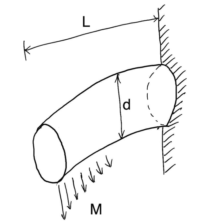
It is important in the case of transmission shafting and shafts running at high speed, where small lateral deflection would cause huge out-of-balance forces. The lateral rigidity is also important for maintaining proper bearing clearances and for correct gear teeth alignment.
If the shaft is of uniform cross-section, then the lateral deflection of a shaft may be obtained by using the deflection formulae as in Strength of Materials.
But when the shaft is of variable cross-section, then the lateral deflection may be determined from the fundamental equation for the elastic curve of a beam, as mentioned below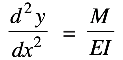
These are the definitions of Torsional Rigidity and Lateral Rigidity and their relation formulas. Let us solve an example problem to understand how these formulas are important.
Example problem to Find Spindle Diameter and Shear Stress in it
A steel spindle transmits 4 kW at 800 rpm. The angular deflection should not exceed 0.25° per meter of the spindle. If the modulus of rigidity for the material of the spindle is 84 GPA, find the diameter of the spindle and the shear stress-induced in the spindle.
Answer:
Given data
Load P = 4 kW = 4000 W
Speed N = 800RPM
Angler twisti in shaft per meter θ = 0.25° = 0.25 π/180 = 0.0044 rad
Length of shaft L = 1 m = 1000 mm
Modulus of rigidity of shaft material G = 84 GPa = 84 × 109 N/m2 = 84 × 103 N/mm2
Finding Diameter of the spindle
Let us say d = Diameter of the spindle in mm.
We can obtain the torque from the power and speed is T = 47740 N-mm
We know that from above
47740/0.0044 = 84 × 103 × (π/32) × d4
d4 = 129 167 × 32 / π
d4 = 1.3 × 10⁶
d = 33.87
We got the spindle shaft diameter as 33.87mm, let us consider the spindle shaft diameter as 35mm.
Finding Shear stress induced in the spindle
Let us say τ = Shear stress induced in the spindle.
We know that the torque transmitted by the spindle (T), from here
47740 = π/16×τ×d3
47740 = π/6×τ(35)3
47740 = 8420 τ
τ = 47 740 / 8420
τ = 5.67
We got the shear stress-induced in the shaft as 5.67 N/mm2 (5.67 MPa)
This is all about the Torsional Rigidity and Lateral Rigidity. Let us know what do you think about this in the comment section below.

Leave a Reply