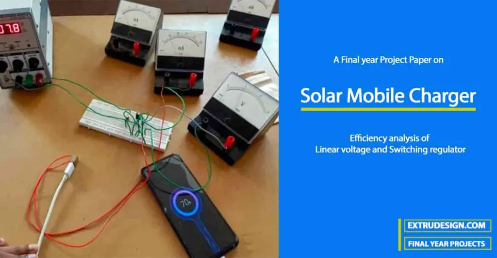
A Final Year Project on “Solar Mobile Charger and Efficiency analysis of Linear voltage and Switching regulator” submitted by Dhayalan R (from Alagappa Chettiar Government College Of Engineering And Technology karaikudi) to extrudesign.com.
Abstract
It works on the principle that when light falls on the solar cells electron holes pairs are created in the n-type emitter and the p-type bases. The generated electrons and holes then diffuse to the junction and are swept away by the electric field, thus producing. certain modules are selected and worked out to suitable specifications. The development of solar chargers goes from the fundamental levels like soldering lamination and making the panel etc. The development charger is planned for 6 volts with incapacity at bright sunlight step down to 5volts using the regulator. In the report, the detailed experimental characteristics of mobile chargers are noted.
In almost all the countries mobile phones are the most popular form of communication. The number of mobile users will surpass 749 million users this year (2020)
and the number is growing as technology is getting better and the cost of production also lowers. However, it becomes very inconvenient for persons occupied with work or traveling long distances as the average lifetime of a mobile phone battery is less than 10 hours. Solar phone chargers use small solar panels to absorb light. This process still forces customers to carry another device along with their cell phones. And also the proposed system, solar-powered charger (SPC) plays an important role in mobile charging during traveling. The sun is the ultimate power source and solar energy is a renewable energy source. The SPC system is eco-friendly and user-friendly. The solar panel used is of a 12v rating. The voltage must be suitably stepped down. So we designed a small charger panel, getting the appropriate voltage and power output through a DC-DC step-down buck converter. We designed a final prototype that should be able to charge any of the commonly used local phones in 10-12 hours of direct sunlight.
1. INTRODUCTION
1.1 NEED FOR SOLAR MOBILE CHARGER
Solar mobile phone chargers use solar panels to charge cell phone batteries. They can be used when no electricity supply is available either mains or for example a vehicle battery and are somethings suggested as a way to charge phones without consuming mains electricity, unlike electrical cell phone charges. Some can also be used as a conventional charger by plugging into an electrical outlet. some charger haves an internal rechargeable battery that is charged in sunlight and then uses to charge a phone others charge the phone directly. there is also a public solar charger for mobile phones which can be installed permanently in public places such as streets, parks, and squares.
Solar cell phone chargers come in different shapes and configurations including folders and types that unfold like petals. they also come in the form of straps, with solar cells on the outer surface and a rechargeable battery inside. solar cell technology limits the effectiveness and practicality of phone solar chargers for everyday use. Phone charger times vary depending on the solar panel size and efficiency or the battery capacity of models with batteries further extending the charge times of solar charges. The fold-out design provides a large solar panel, hence higher charger current, and is compact when not in use.
Solar chargers can be used to charge other rechargeable devices with requirements similar to a mobile phone such as a blue tooth headset and music players. The solar charger used to charge directly rather than by using an internal battery can damage a phone if the output is not well controlled, for example by supplying excessive voltage in bridge sunlight. In less bright light, although there is electrical output it may be too low to support charging it will not just charge slower.
1.2 Efficiency analysis
Efficiency is a measurement of how much power is wasted by the regulator. As the efficiency is calculated by the output power by the input power. So if the output power is the same as the input power then the efficiency is 100% and the regulator wastes no power. This is the ideal but unattainable scenario. Most switching regulators have an efficiency between 80- 90%.this efficiency of a linear regulator varies with the ratio of the input voltage to the output voltage. This is because for a linear regulator the input current is always essentially identical to the output current.
Since power is equal to the voltage times currents in the efficiency equation cancel out only leaving the voltage. This means the bigger the difference between the input voltage and the output voltage the worse the efficiency for a linear regulator.
1.3 Literature Review
The current market leader in efficient solar energy modules is Sun Power, whose solar panels have a conversion ratio of 19.3%, with Sanyo having the most efficient modules at 20.4%. However, a whole range of other companies (Holo Sun, Gamma Solar, Nano Horizons) is emerging which are also offering innovations in photovoltaic modules, with a conversion ratio of around 18%. These innovations embrace power generation on the front and back sides and increased outputs; but, most of these companies have not yet produced working systems from their design plans, and area unit principally still actively rising the technology.
The term “photovoltaic” comes from the Greek (photo) suggests that “light”, and “voltaic”, means electric, from the name of the Italian physicist “VOLTA “after whom a unit of electro-motive force, the volt is named. The sun could be a star created from atomic number 1 and element gas and it radiates a huge quantity of energy each second. A solar cell is an associate degree device that converts the energy of sunshine directly into electricity by electrical
phenomenon result. The operation of an electrical phenomenon (PV) cell needs three basic 3
attributes: The absorption of sunshine, generating either electron-hole pairs or excitons.The separation of charge carriers of opposite types.The separate extraction of these carriers to associate degree external circuit. In contrast, a solar thermal collector collects heat by absSolar cell phone chargers use solar panels to charge cell phone batteries. They are an alternative to traditional electrical telephones.
Pragnesh B. Gohil, UG. Digvijay P. Jadav, UG. Chirag N. Katakiya, Prof. Jaydipsinh B. Zala proposed that they follow like an example of any electrical system. It must have a source, a function, and an output. For our source, we will be using solar panels optimized with solar tracking. The system will contain the microcontroller to act as a charge controller and an inverter to convert from 12 Volt DC stored in the batteries to 110 Volt AC as the output. Figure 2 below shows a block diagram of the system. The solar tracker would be affixed to the solar panel and would relay information to the microcontroller.
The merchandise ought to tobe simple to envision and may minimize style complexness, however ought to be sturdy and ready to resist hormones handled on a routine. It ought to be esthetically appealing and easy to use so the general public will use it while not help, the merchandise ought to be ready to charge a telephone during a similar time-frame to the current technique, that means inside half dozen hours for an entire charge cycle and the merchandise ought to be versatile and charge the various telephone brands out there within the community. This paper analyzes the potential power sources for sensor nodes. Analysis between power sources, such as batteries power and Solar cell power from energy harvesting for sensor node.
2. Proposed system Hardware And Architecture
2.1 List of Hardware required to design a Solar Mobile Charger
- Solar panel 7.5 volts *2
- Voltage regulator IC 7805
- Capacitor
- USB connector
- Mosfet
- Diode
- Inductor
- IC 555
- Resister
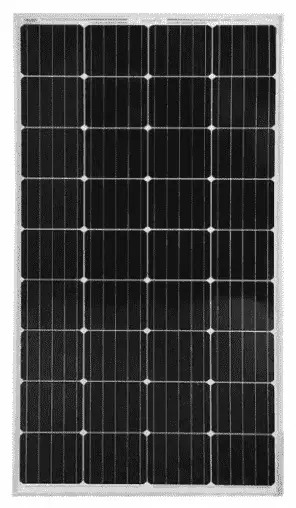
2.2 SOLAR PANEL
Solar panels are those devices that are used to absorb the sun’s rays and convert them into electricity or heat. A solar panel is a collection of solar (or photovoltaic) cells, which can be used to generate electricity through the photovoltaic effect. These cells are arranged in a grid-like pattern on the surface of solar panels. Thus, it may also be described as a set of photovoltaic modules, mounted on a structure supporting it.
A photovoltaic (PV) module is a packaged and connected assembly of 6×10 solar cells. When it comes to wear-and-tear, these panels are very hardy. Solar panels wear out extremely slow. In a year, their effectiveness decreases only about one to two percent. Most solar panels are made up using crystalline silicon solar cells. Installation of solar panels in homes helps in combating the harmful emissions of greenhouse gases and thus helps reduce global warming.
Solar panels do not lead to any form of pollution and are clean. They also decrease our reliance on fossil fuels and traditional power sources. These days, solar panels are used in wide-ranging electronic equipment like calculators, which work as long as sunlight is available. However, the only major drawback of solar panels is that they are quite costly. Also, solar panels are installed outdoors as they need sunlight to get charged.
ADVANTAGES:
- Solar energy is a renewable energy source.
- Solar energy comes in free of energy.
- Solar cells panel on the solar charge does not require much maintenance
- It also helps reduce cost such as the solar charger source of energy is free
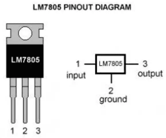
2.3 VOLTAGE REGULATOR IC 7508
A voltage regulator is a system designed to automatically maintain a constant voltage. A voltage regulator may use a simple feedback forward design or may include feedback. It may use an electrochemical mechanism or electronic components. Depending on the design, it may be used to regulate one or more AC or DC voltage
CAPACITOR
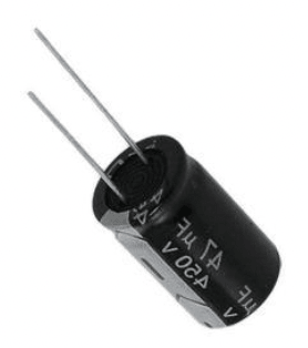
A capacitor is a device that stores electrical energy in an electric field. It is a passive electronic component with two terminals. The effect of a capacitor is known as capacitance. While some capacitance exists between any two electrical conductors in proximity in a circuit, a capacitor is a component designed to add capacitance to a circuit. The capacitor was originally known as a condenser or condensation. This name and its cognates are still widely used in many languages, but rarely in English, one notable exception being condenser microphones, also called capacitor microphones.
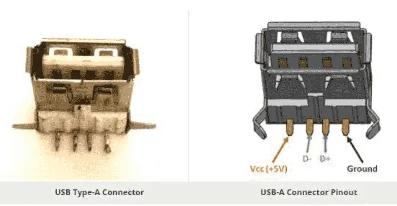
USB CONNECTOR
USB-A female is the standard “host” connector type. This is found on computers, hubs, or any device intended to have peripherals plugged into it. It is also possible to
find extension cables with a female A connector and a male A connector on the other end.
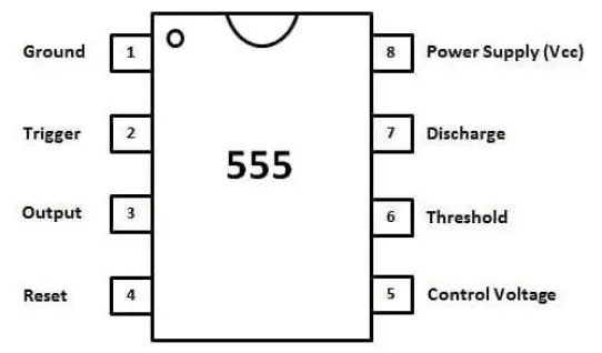
IC 555
The 555 timer IC is an integrated circuit used in a variety of timer, delay, pulse generation, and oscillator applications.
MOSFET
The MOSFET transistor is a semiconductor device that is widely used for switching purposes and for the amplification of electronic signals in electronic devices. A MOSFET is either a core or integrated circuit where it is designed and fabricated in a single chip because the device is available in very small sizes. The introduction of the MOSFET device has brought a change in the domain of switching in electronics.
2.4 BUCK CONVERTER
A buck converter (step-down converter) is a DC-to-DC power converter that steps down voltage (while drawing less average current) from its input. It is a class of switched-mode power supply (SMPS) that typically contains at least two semiconductors (a diode and a transistor although modern buck converters frequently replace the diode with a second the transistor used for synchronous rectification) and at least one energy storage element a capacitor, inductor, or the two in combination. To reduce voltage ripple filters made of the capacitor is normally added to such a converter’s output and input. switching converters (such as buck converters) provide much greater power efficiency as DC-to-DC converters than linear regulators, which are simpler circuits that lower voltages by dissipating power as heat, but do not step up output current, The efficiency of buck converters can be very high often over 90% making them useful for tasks such as converting a computer’s main supply voltage, which is usually 12 V down to lower voltages needed by USB, DRAM.

While performing the analysis of the Buck converter, we have to keep in the mind that
- The inductor current is continuous and, this is made possible by selecting an appropriate value of L.
- The inductor current in steady state rises from a value with a positive slope to a maximum value during the ON state and then drops back down to the initial value with a negative slope. Therefore the net change of the inductor current over anyone’s complete cycle is zero.
3. Circuit Diagram of Solar Mobile Charger system
3.1 Block Diagram
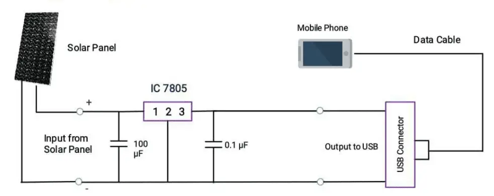
Explanation:
Solder all the components on a PCB as shown in the circuit diagram. To test the regulator circuit, connect voltage between 8 V and 18V to the input of the voltage regulator. Now, measure the output. The output should be constant and it can be any value between 4.75 V and 5.25V. If so, your circuit is working properly Solder the positive output wire of the voltage regulator to the USB’s positive. Similarly, connect the negative output of the regulator to the negative of USB.
The USB port must be fixed properly to the PCB. Next, connect the solar panel to the input of the voltage regulator (positive of solar panel to the positive input of voltage regulator and negative of solar panel to negative input). Once everything is connected, measure the output voltage in open sunlight. It should be around 5V. Now, connect your mobile phone and you will see it charging.
3.2 Block diagram of buck converter Solar Mobile Charger

Explanation:
The block diagram of the system contains a solar panel, buck converter, and battery. The solar panel is used to convert solar energy to electrical energy. The normal voltage rating of the solar panel used is 12V. The principle used is PHOTOELECTRIC EFFECT for the conversion of solar energy to electrical energy. When light is incident upon a material surface; the electrons present in the valence band absorb energy and get excited. They jump 12 to the conduction band and become free. Some reach a junction where they are accelerated into a different material by a Galvani potential. This generates an electromotive force, and thus electric energy. Buck converter is a dc-dc converter, which comprises of MOSFET switch (IRF250N), inductor, capacitor, and diode. Buck converter reduces the input voltage to the desired voltage of charging. The battery is charged from this output of the buck converter.
4. SIMULATION
4.1 Simulation using Voltage Regulator mobile charge
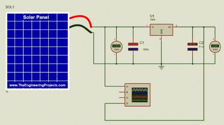
4.2 Output waveform
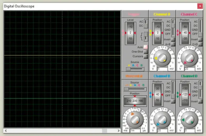
Output reading:
| Input Voltage(V) | Input Curren(mA) | Output Voltage | Output Current | Efficiency(%) |
| 6 | 130 | 3.6 | 110 | 60% |
| 7 | 230 | 4.5 | 215 | 64% |
| 8 | 240 | 4.5 | 225 | 56% |
| 9 | 220 | 4.5 | 190 | 50% |
| 10 | 200 | 4.5 | 180 | 45% |
4.3 Simulation using buck converter mobile charger
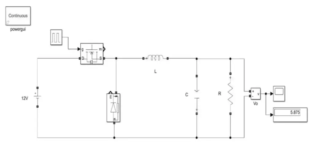
Description
A buck converter is a DC/DC power converter that steps down the voltage from its input (source) to its output (load). In continuous conduction mode (current through the inductor never falls to zero), the theoretical transfer function of the buck converter is:
Vout/Vin = D
where D is the duty cycle
In this example, the converter is feeding an RC load from a 200 V source and the PWM frequency is set to 10 kHz.
4.3 CALCULATION FOR BUCK CONVERTER
Calculation of Duty Cycle:
Vin=12
Vout = 5
D = Vout/Vin
= 5/12
= 0.416
Calculation of Minimum Inductance:
Lmin= (1-D)2R/2f
= (0.62)*100/(2*10000)
= 1.8*10-3 L
= 1.25*1.8*10-3
= 2.25 mH
Calculation of Capacitance:
C = D/Rrf
= 0.4/100*0.01*10000
= 40 uF
Time period:
T = 1/1000
=1*10-4
=0.1 mS
OUTPUT WAVEFORM:
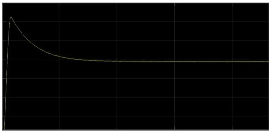
Simulation Output Reading:
| Input Voltage | Output Voltage |
| 8 | 3.36 |
| 9 | 4.24 |
| 10 | 4.54 |
| 11 | 5.22 |
| 12 | 5.8 |
5. HARDWARE IMPLEMENTATION
5.1 Voltage regulator mobile charge
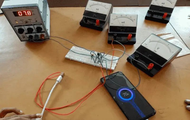
VOLTAGE REGULATOR Vs BUCK CONVERTER
- Buck converter converts DC into a lower voltage DC. It has a constant transformer ratio.
- Buck regulator is used to maintain a constant voltage DC output for a varying voltage DC input. So the transformation ratio keeps changing hence in order to keep the output voltage is constant
6. CONCLUSION
Solar act as good power supplies in bright sunlight. The only problem is the unregulated voltage due to the variation in the intensity of light. A voltage regulator is used to solve this problem by regulating the output voltage. The charge so obtained is stored in the battery and is given to the respective loads. The charge
present in this battery is analyzed and displayed
on an LCD. Solar-powered cell phone chargers can be a better
alternative to electrical cell phone chargers. It will make the running cost of mobile phones reduced. For that purpose-designed an eco-friendly solar-powered charger (SPC) for mobile charging which utilizes an effective converter topology and microcontroller to ensure effective utilization of solar energy. A SOLAR POWER MOBILE CHARGER can accommodate almost any model cell phone. It can use the sun’s energy to recharge a cell phone.
REFERENCE
- http://en.wikipedia.org/wiki/Electrical_resistance_and_conductance
- http://science.howstuffworks.com/environmental/energy/solar- cell1.htm
- http://en.wikipedia.org/wiki/Electrical_element.htm
- http://www.allaboutcircuits.com/vol_3/chpt_4/1.htm
- Solar Electricity Engineering of Photovoltaic System, by Lorezo E.
- Power Electronics, by Bhimbra P.S.
- An Energy-aware Survey on Mobile-phone Chargers, p. 8. Bonner, J. (2012), Portable Solar Panel Charging Station, p.31.
- Renewable Energy and Energy Efficiency Incentives: A summary of Federal Programs, p.5. de Groot, H. (2008),
- http://www.tpub.com/content/neets/14175/css/14175_130.htm
- http://www.solar-facts.com/panels/
- http://www.webbikeworld.com/r3/motorcycle-battery-charger/solar batterycharger/pulsetech-solar-battery-charger.htm
- http://www.national.com/ds/LM/LM723.pdf
Credit: This Project “Solar Mobile Charger and Efficiency analysis of Linear voltage and Switching regulator” was completed by Dhayalan R, Akash D, Jabez E Joshua, and Karthik M under the supervision of Dr. K. BASKARAN (HOD) and Prof.K.Padmanaban from the department of Electrical And Electronics Engineering of Alagappa Chettiar Government College Of Engineering And Technology karaikudi.

Leave a Reply