
1.INTRODUCTION
1.1 HEAT EXCHANGERS
The heat exchanger is equipment which transfers energy from a hot fluid to cold Fluid. While the fluid is passing through the heat exchanger, the temperature of Fluid changes along the length of the heat exchanger. The present study focuses mainly on the design of heat exchanger known to be shell and tube, heat exchanger.
A shell and tube heat exchanger is a class of heat exchanger designs. It is the most common type of heat exchanger in oil refineries and other large chemical processes and is suited for higher pressure applications. This type of heat exchanger consists of a shell (a large pressure vessel) with a bundle of tubes inside it. One fluid run-through the tubes and another fluid flows over the tubes (through the shell) to transfer heat between the two fluids. Heat exchangers are devises to recover heat between two process streams.
The use of heat exchangers is extensive in power plants, refrigeration and air-conditioning systems, Space Chemical, Nuclear, Petrochemical, and Cryogenic industries. Heat exchangers appear in a variety of shapes and size It can be as huge as a power plant condenser transferring hundreds of Megawatts of heat or as tiny as an electronic chip cooler which transfers only a few Watts of thermal energy.
Heat exchangers are one of the most used equipment in the process industries. Heat exchangers are used to transferring heat between two process streams. One can realize their usage that any process which involves cooling, heating, condensation, boiling or evaporation will require a heat exchanger for this purpose. Process fluids, usually are heated or cooled before the process undergo a phase change. Different heat exchangers are named according to their application. For example, heat exchangers being used to condense are known as condensers, similarly, heat exchanger for boiling purposes are called boilers. Performance and efficiency of heat exchangers are measured through the amount of heat transfer using the least area of heat transfer and pressure drop. A better presentation of its efficiency is done by calculating the overall heat transfer coefficient. Pressure drop and area required for a certain amount of heat transfer provide an insight into the capital cost and power requirements (Running cost) of a heat exchanger. Usually, there is lots of literature and theories to design a heat exchanger according to the requirements.
Baffles are used to support the tubes for structural rigidity, preventing tube vibration and sagging and to divert the flow across the bundle to obtain a higher heat transfer coefficient. Baffle spacing (B) is the centre line distance between two adjacent baffles, Baffle is provided with a cut (Bc) which is expressed as the percentage of the segment height to shell inside diameter. Baffle cut can vary between 15% and 45% of the shell inside diameter
Factors of Heat exchangers
- Construction
- Flow arrangement
- Number of shells
- Contact between the processing streams
- Compactness
Heat transfer mechanism Shell and tube heat exchangers consist of a series of tubes. One set of these tubes contains the fluid that must be either heated or cooled. The second fluid runs over the tubes that are being heated or cooled so that it can either provide the heat or absorb the heat required. A set of tubes is called the tube bundle and can be made up of several types of tubes: plain, longitudinally finned, etc. Shell and tube heat exchangers are typically used for high-pressure applications (with pressures greater than 30 bar and temperatures greater than 2600 c
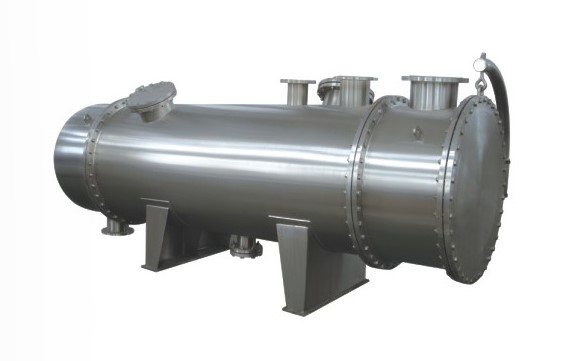
A heat exchanger is a device that is used to transfer thermal energy (enthalpy) between two or more fluids, between a solid surface and a fluid, or between solid particulates and a fluid, at different temperatures and in thermal contact. In heat exchangers, there are usually no external heat and work interactions. Typical applications involve heating or cooling of a fluid stream of concern and evaporation or condensation of single- or multicomponent fluid streams.
In other applications, the objective may be to recover or reject heat or sterilize, pasteurize, fractionate, distil, concentrate, crystallize, or control a process fluid. In a few heat exchangers, the fluids exchanging heat are in direct contact. In most heat exchangers, heat transfer between fluids takes place through a separating wall or into and out of a wall in a transient manner. In many heat exchangers, the fluids are separated by a heat transfer surface, and ideally, they do not mix or leak.
Such exchanges are referred to as direct transfer type, or simply recuperators. In contrast, exchangers in which there is intermittent heat exchange between the hot and cold fluids—via thermal energy storage and release through the exchanger surface or matrix— are referred to as indirect transfer type, or simply regenerators. Such exchangers usually have fluid leakage from one fluid stream to the other, due to pressure differences and matrix rotation/valve switching. Common examples of heat exchangers are shell-and-tube exchangers, automobile radiators, condensers, evaporators, air preheaters, and cooling towers. If no phase change occurs in any of the fluids in the exchanger, it is sometimes referred to as a sensible heat exchanger.
. There could be internal thermal energy sources in the exchangers, such as in electric heaters and nuclear fuel elements. Combustion and chemical reaction may take place within the exchanger, such as in boilers, fired heaters, and fluidized-bed exchangers. Mechanical devices may be used in some exchangers such as in scraped surface exchangers, agitated vessels, and stirred tank reactors. However, in a heat pipe heat exchanger, the heat pipe not only acts as a separating wall, but also facilitates the transfer of heat by condensation, evaporation, and conduction of the working fluid inside the heat pipe. In general, if the fluids are immiscible, the separating wall may be eliminated, and the interface between the fluids replaces a heat transfer surface, as in a direct-contact heat exchanger.
A heat exchanger consists of heat transfer elements such as a core or matrix containing the heat transfer surface, and fluid distribution elements such as headers, manifolds, tanks, inlet and outlet nozzles or pipes, or seals. Usually, there are no moving parts in a heat exchanger; however, there are exceptions, such as a rotary regenerative exchanger (in which the matrix is mechanically driven to rotate at some design speed) or a scraped surface heat exchanger. The heat transfer surface is a surface of the exchanger core that is in direct contact with fluids and through which heat is transferred by conduction. That portion of the surface that is in direct contact with both the hot and cold fluids and transfers heat between them is referred to as the primary or direct surface. To increase the heat transfer area, appendages may be intimately connected to the primary surface to provide an extended, secondary, or indirect surface. These extended surface elements are referred to as fins. Thus, heat is conducted through the fin and convicted (and/or radiated) from the fin (through the surface area) to the surrounding fluid or vice versa, depending on whether the fin is being cooled or heated.
As a result, the addition of fins to the primary surface reduces the thermal resistance on that side and thereby increases the total heat transfer from the surface for the same temperature difference. Fins may form flow passages for the individual fluids but do not separate the two (or more) fluids of the exchanger. These secondary surfaces or fins may also be introduced primarily for structural strength purposes or to provide thorough mixing of a highly viscous liquid. Not only are heat exchangers often used in the process, power, petroleum, transportation, air-conditioning, refrigeration, cryogenic, heat recovery, alternative fuel, and manufacturing industries, they also serve as key components of many industrial products available in the marketplace. These exchanges can be classified in many different ways. We will classify them according to transfer processes, a number of fluids, and heat transfer mechanisms. Conventional heat exchangers are further classified according to construction type and flow arrangements. Another arbitrary classification can be made, based on the heat transfer surface area/volume ratio, into compact and noncompact heat exchangers.
This classification is made because the type of equipment, fields of applications, and design techniques generally differ. All these classifications are summarized in Fig. 1.1 and discussed further in this chapter. Heat exchangers can also be classified according to the process function, as outlined in Fig. 1.2. However, they are not discussed here and the reader may refer to Shah and Mueller (1988). Additional ways to classify heat exchangers are by fluid type (gas–gas, gas–liquid, liquid-liquid, gas two-phase, liquid two-phase, etc.), industry, and so on, but we do not cover such classifications in this chapter
A heat exchanger is a device built for efficient heat transfer from one medium to another in order to carry and process energy. It is widely used in petroleum refineries, chemical plants, petrochemical plants, natural gas processing, air conditioning, refrigeration, and automotive applications. The most commonly used type of heat exchanger is the shell-and-tube heat exchanger. To increase the heat transfer rate in shell and tube type heat exchanger, the segmental baffles are introduced inside the cover pipe. The flow arrangement used in the analysis is laminar counterflow as it is more efficient than a parallel flow arrangement. The different orientations of baffles in the heat exchanger are given in Figure 1
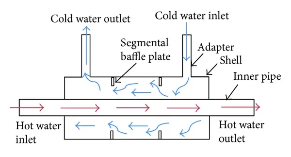
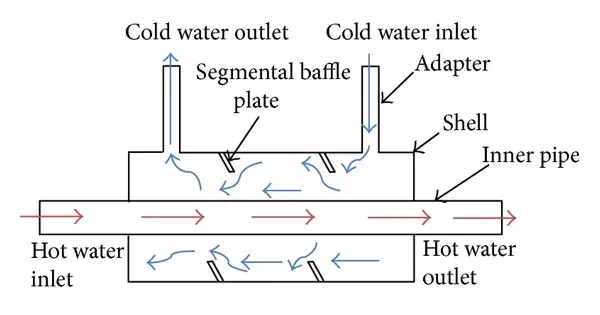
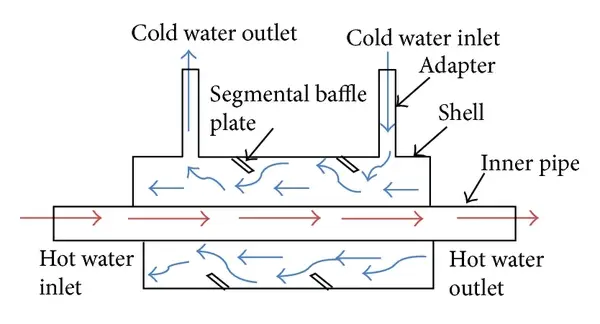
Shell-and-tube type heat exchanger having (a) 0°, (b) 30°, and (c) 60° baffle angles.
The common focus of the publication is to predict the variation of LMTD, heat transfer coefficient, Nusselt number, and pressure drop with a change in values of Reynolds number for 0°, 30°, and 60° baffles situated in the heat exchanger as shown in Figure 1. The Reynolds number will be varying from 303 to 1516.
The enhancement of Nusselt number with the increase in Reynolds number will be presented by Zohir, Tandiroglu, and Promvonge. The heat transfer coefficient values are calculated using the log-mean-temperature-difference (LMTD)method from the temperature difference and the heat transfer area. Gay et al. and Mehrabian l. concluded that the heat transfer coefficient increases with inserting baffles. Thundil et al. observed that the pressure drop will decrease with increasing baffle inclination angle and the heat transfer rate increases with increasing baffle inclination angle.
Generally, the most basic compact heat exchangers have a 50% less than the volume of that of a comparable shell-and-tube heat exchanger, for a given work. These exchanges are generally built of circular tubes, although elliptical, rectangular, or round/flat twisted tubes have also been used in some applications.
There is considerable flexibility in the design because the core geometry can be varied easily by changing the tube diameter, length, and arrangement. Tubular exchangers can be designed for high pressures relative to the environment and high-pressure differences between the fluids. Tubular exchangers are used primarily for liquid-to-liquid and liquid-to-phase change (condensing or evaporating) heat transfer applications
They are used for gas-to-liquid and gas-to-gas heat transfer applications primarily when the operating temperature and/ or pressure is very high or fouling is a severe problem on at least one fluid side and no other types of exchangers would work. These exchanges may be classified as shell-and-tube, double-pipe, and spiral tube exchangers. They are all prime surface exchangers except for exchangers having fins outside/inside tubes.
1.2 CLASSIFICATION OF TRANSFER PROCESSES
Heat exchangers are classified according to transfer processes into indirect-and direct contact types.
Indirect-Contact Heat Exchangers:
In an indirect-contact heat exchanger, the fluid streams remain separate and the heat transfers continuously through an impervious dividing wall or into and out of a wall in a transient manner. Thus, ideally, there is no direct contact between thermally interacting fluids. This type of heat exchanger also referred to as a surface heat exchanger, can be further classified into direct-transfer type, storage type, and fluidized-bed exchangers.
Direct -Contact Heat Exchangers:
In this type, heat transfers continuously from the hot fluid to the cold fluid through a dividing wall. Although a simultaneous flow of two (or more) fluids is required in the exchanger, there are no direct mixing of the two (or more) fluids because each fluid flows in separate fluid passages. In general, there are no moving parts in most such heat exchangers. This type of exchanger is designated as a recuperative heat exchanger or simply as a recuperator.
Flexibility in distributing surface area on the hot and cold sides as warranted by design considerations. Generally, substantial cost, weight, or volume savings. The important design and operating considerations for compact extended-surface exchangers are as follows. Usually, at least one of the fluids is a gas having a low h value. Fluids must be clean and relatively noncorrosive because of low-Dh flow passages and no easy techniques for cleaning.
The fluid pumping power (and hence the pressure drop) is often as important as the heat transfer rate. Operating pressures and temperatures are somewhat limited compared to shell and-tube exchangers, due to joining of the fins to plates or tubes by brazing, mechanical expansion, and so on. With the use of highly compact surfaces, the resulting shape of the exchanger is one having a large frontal area and a short flow length; the header design of a compact heat exchanger is thus important for achieving uniform flow distribution among very large numbers of small flow passages.
The market potential must be large enough to warrant the sizable initial manufacturing tooling and equipment costs. Fouling is a major potential problem in compact heat exchangers (except for plate-and-frame heat exchangers), particularly those having a variety of fin geometries or very fine circular or noncircular flow passages that cannot be cleaned mechanically. Chemical cleaning may be possible; thermal baking and subsequent rinsing are possible for small units. { Hence, extended-surface compact heat exchangers may not be used in heavy fouling applications. Nonfouling fluids are used where permissible, such as clean air or gases, light hydrocarbons, and refrigerants.
2. Literature Review
In designing of shell and tube heat exchangers, authors paid attention to analyzing this problem both experimentally and theoretically. Kern provides correction factor charts for a different number of shells and even number of tube passes.
He presented the correction factor F, as a function of two variables R and S, which depends on the inlet and exit temperatures of the heat exchanger of both the fluids. Roetzel and Nicole have recognized the potential usefulness of explicit representations of LMTD Correction factors in developing computerized packages for heat exchanger design. Tinker has suggested a schematic flow pattern, which divided the shell –side flow into a number of individual streams. Tinkers model has been the basis of “Stream analysis method”, which utilizes a rigorous reiterative approach and it is particularly suitable for computer calculations rather than hand calculations
Saunders in his book proposed a practical method and simple design factors are provided and the method is used rapidly for a fixed set of geometrical parameters. In his work, the correction factors are for heat transfer and pressure drop correlations. Wills and Johnston [5] in his article developed a stream analysis method that is visible for hand calculations. They developed a new and accurate hand calculation method for shell and tube pressure drop and flow distributions Reppich and Zagermann in his paper offers a computer-based design model to determine the optimum dimensions of segmentally baffled shell-and-tube heat exchangers by calculating optimum shell-side, tube – side pressure drops from the equation provided in his work. The six optimized dimensional parameters are a number of tubes, tube length, shell diameter, a number of baffles, baffle cut, and baffle spacing. The proposed model also carries out also cost analysis. Lam and Lo in his article presented the flow patterns and a corresponding analysis of four circular cylinders subjected to cross flow. Experiments were carried out at subcritical Reynolds number of 2100. Square arrangement of the cylinders with varying spacing ratios and angles of incidents were examined
Moghadassi and Hosseini had given the importance of heat exchangers in chemical and petrochemical industries, Heat exchangers analysis and heat translate calculations are provided. The conventional and prevalent methods (such as KERN method) are presented. Liljana Markovska and Vera Mesko gave optimization of the shell-and-tube-heat exchanger are accomplished by use of the optimizer software package. The objective function is defined together with the implicit constraint. The simultaneous equation solving method is used to solve the equations that describe the process. Lebele-Alawa and Victor Egwanwo presented a numerical method of solution, capable of accounting for temperature dependent variation of fluid properties and heat transfer. Field data were collected for three different industrial heat exchangers and basic governing equations were applied. The parameters analyzed include the outlet temperatures, the heat transfer coefficients and the heat exchanger effectiveness. Naik and Matawala studied design and assessment of counterflow shell and tube heat exchanger by entropy generation minimization method
A Shell and tube heat exchanger is a device in which energy is transferred from one fluid to another across a solid surface. Exchanger analysis and design, therefore, involve both convection and conduction. Two important problems in heat exchanger analysis are (1) rating existing heat exchangers and (ii) sizing heat exchangers for a particular application. Rating involves the determination of the rate of heat transfer, the change in temperature of the two fluids and the pressure drop across the heat exchanger. Sizing involves selection of a specific heat exchanger from those currently available or determining the dimensions for the design of a new heat exchanger, given the required rate of heat transfer and allowable pressure drop. The LMTD method can be readily used when the inlet and outlet temperatures of both the hot and cold fluids are known. When the outlet temperatures are not known, the LMTD can only be used in an iterative scheme. In this case, the effectiveness-NTU method can be used to simplify the analysis.
The thermal analysis of a shell and tube heat exchanger involves the determination of the overall heat-transfer coefficient from the individual film coefficients, and (Kern, 1965). The shell-side coefficient presents the greatest difficulty due to the very complex nature of the flow in the shell. In addition, if the exchanger employs multiple tube passes, then the LMTD correction factor must be used in calculating the mean temperature difference in the exchanger.
For the turbulent flow regime (Re ≥ 104 ), the following correlation is widely used (Perth, 2007).
Nu = Re0.8 Pr1/3 (µ/µw) 0.14
Where, Nu = Nusselt Number = hd/k
Re = Reynold’s Number = DVρ/µ
Pr = Prandtl Number = cpµ/k
D = Inside diameter of the pipe V = average fluid velocity. Cp,µ,ρ,k = Fluid properties at avg. bulk temperature. µw = Fluid viscosity evaluated at the average wall temperature. Eq. (1) holds good for 0.5 ≤ Pr ≥ 17,000 & for pipes L/D ≥ 10. However, for short pipes 10 ≤ L/D ≥ 60, the right-hand side of the equation is often multiplied by the factor [ 1+(D/L)2/3] to correct for the entrance and exit effects. (Serth 2007). For laminar flow in circular pipes (Re < 2100), the seiderTate correlation takes the form : Nu = 1.86[RePrD/L]1/3 (µ/µw) 0.14. This equation is valid for 0.5< Pr < Re < 104 ), the Hausen correlation is: Nu = 0.116(Re2/3 – 125) Pr1/3(µ/µw) 0.14 (1+(D/L)2/3). (3) In computing the tube-side coefficient hi it is assumed that all tubes in the exchanger are exposed to the same thermal and hydraulic conditions. The value of hi is then the same for all tubes, and the calculation can be made for a single tube. Equations (1), (2), or (3) were used, depending on the flow regime. The tube fluid heat transfer coefficient, hi, can be calculated using; hi= (Nuk/Di) (4) The Delaware method (Serth, 2007) was used to compute the shell-side heat transfer coefficient, ho. In the equation for the overall heat transfer coefficient, the temperature difference, Δtm, is the mean temperature difference between the two fluid streams.
B. Jayachandriah & K. Rajasekhar [2] An attempt is made in this paper is for the Design of shell and tube heat exchangers by modelling in CATIA V5 by taking the Inner Diameter of shell is 400 mm, length of the shell is 700 mm and Outer diameter of tube is 12.5mm, length of Tube is 800mm and Shell material as Steel 1008, Tube material as Copper and Brass.
The effect of fouling is allowed for in the design by including the inside and outside fouling coefficients. Kern (1965) presented typical values for the fouling factors for common process service fluids used in plane tubes (not finned tubes). The fouling factor for the exchanger is given as (Serth, 2007);
Design problems frequently include specifications of the maximum allowable pressure drops in the two streams. In that case, pressure drops for both streams would have to be calculated in order to determine the hydraulic suitability of the heat exchanger. The pressure drop due to fluid friction in the tubes is given by Equation (15) with the length of the flow path set to the tube length times the number of tube passes (Serth, 2007).
3. TYPES OF HEAT EXCHANGERS
What is Heat exchangers?
A Heat exchanger is devices that facilitate the exchange of heat between two fluids that are at different temperatures while keeping them from mixing with each other.
Different types of Heat Exchangers:
- SHELL AND TUBE HEAT EXCHANGER
- PLATE HEAT EXCHANGER
- REGENERATIVE HEAT EXCHANGER
- ADIABATIC HEAT EXCHANGER
3.1 SHELL AND TUBE HEAT EXCHANGER
A Shell and tube heat exchanger is a class of heat exchanger designs. It is the most common type of heat exchanger in oil refineries and other large chemical processes and is suited for higher-pressure applications. As its name implies, this type of heat exchanger consists of a shell (a large pressure vessel) with a bundle of tubes inside it. One fluid runs through the tubes, and another fluid flows over the tubes (through the shell) to transfer heat between the two fluids. The set of tubes is called a tube bundle and may be composed of several types of tubes: plain, longitudinally finned, etc.
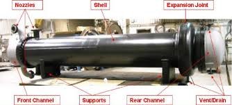
This exchanger is generally built of a bundle of round tubes mounted in a cylindrical shell with the tube axis parallel to that of the shell. One fluid flows inside the tubes, the other flows across and along the tubes. The major components of this exchanger are tubes (or tube bundle), shell, frontend head, rear-end head, baffles, and tube sheets, and are described briefly later in this subsection. For further details, refer to Section 1
. A variety of different internal constructions are used in shell-and-tube exchangers, depending on the desired heat transfer and pressure drop performance and the methods employed to reduce thermal stresses, to prevent leakages, to provide for ease of cleaning, to contain operating pressures and temperatures, to control corrosion, to accommodate highly asymmetric flows, and so on. Shell-and-tube exchangers are classified and constructed in accordance with the widely used TEMA (Tubular Exchanger Manufacturers Association) standards (TEMA, 1999), DIN and other standards in Europe and elsewhere, and ASME (American Society of Mechanical Engineers) boiler and pressure vessel codes.
TEMA has developed a notation system to designate major types of shell-and-tube exchangers. In this system, each exchanger is designated by a three-letter combination, the first letter indicating the front-end head type, the second the shell type, and the third the rear-end head type. These are identified in Fig. 1.6. Some common shell-and-tube exchangers are AES, BEM, AEP, CFU, AKT, and AJW. It should be emphasized that there are other special types of shell-and-tube exchangers commercially available that have front- and rear-end heads different from those. Those exchangers may not be identifiable by the TEMA letter designation.
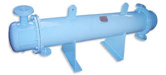
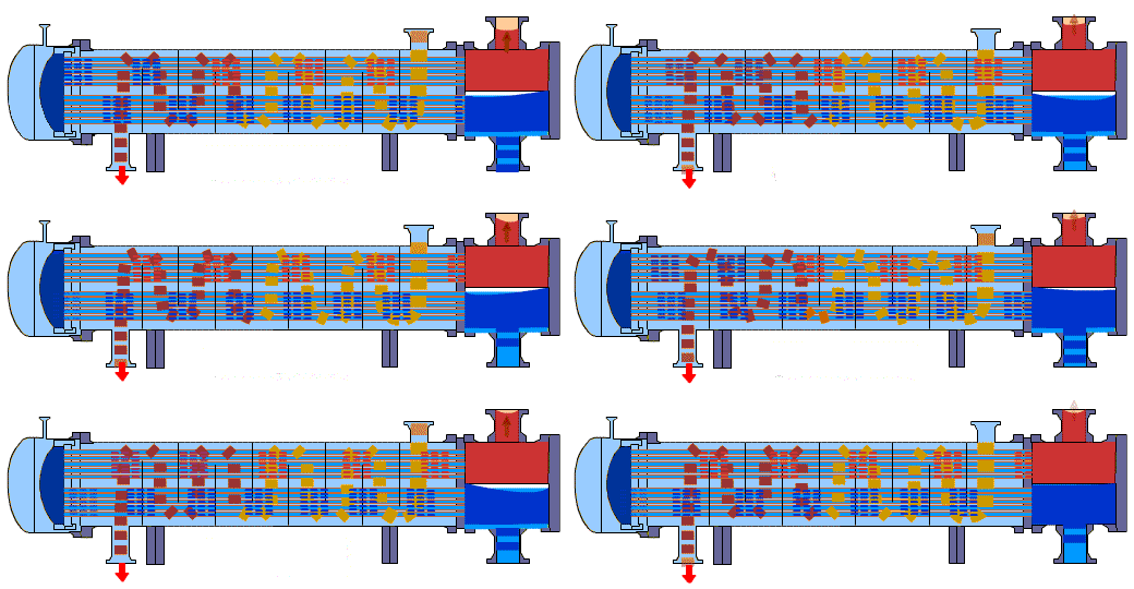
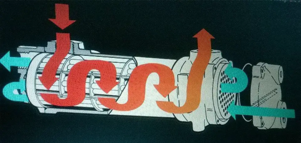
The flow process of shell and tube heat exchanger the heat transfer between hot fluid and cold fluid
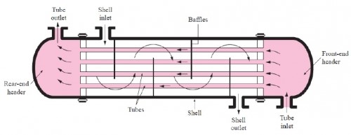
Baffles are used to support the tubes for structural rigidity, preventing tube vibration and sagging and to divert the flow across the bundle to obtain a higher heat transfer coefficient
3.2 PLATE HEAT EXCHANGER:
The plate heat exchangers in this brochure are suitable for the majority of relatively uncomplicated heat transfer jobs using water, oil or glycol as the media. When it comes to the effectiveness of heat transfer and economical operation, the plate heat exchanger is unsurpassed in HVAC, refrigeration, sanitary water heating as well as industrial heating and cooling applications. The Alfa Laval product range of plate heat exchangers is extensive.
From the largest units with maximum surfaces up to 3,000 m² and flow rates of approximately 5,000 m³/h to smaller units with maximum heat transfer areas of less than 1 m² and flow rates from 0.18 m³/h. Every single heat exchanger in the catalogue can perform a range of duties. Applications include the heating and cooling of different fluids in factories, HVAC applications, process cooling, components in air conditioning equipment etc. The list of applications is considerable. Not all types of our plate heat exchangers are included in this brochure. If you require more information, please do not hesitate to contact us.
A plate heat exchanger consists of a number of heat transfer plates which are held in place between a fixed plate and a loose pressure plate to form a complete unit. Each heat transfer plate has a gasket arrangement which provides two separate channel systems. The arrangement of the gaskets (field and ring gaskets) results in through flow in single channels so that the primary and secondary media are in counter-current flow. The media cannot be mixed because of the gasket design. The plates are corrugated, which creates turbulence in the fluids as they flow through the unit. This turbulence, in association with the ratio of the volume of the media to the size of the heat exchanger, gives an effective heat transfer coefficient.
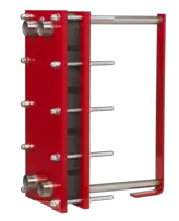
The components consist of a fixed end plate, connections and a loose pressure plate, with carrier bars mounted between them. The plates are hung from the top carrier bar. The carrier bars also serve to position the heat transfer plates. The single plates are pulled together to form a plate pack by means of tightening bolts.
A plate heat exchanger is a type of heat exchanger that uses metal plates to transfer heat between two fluids. This has a major advantage over a conventional heat exchanger in that the fluids are exposed to a much larger surface area because the fluids spread out over the plates. This facilitates the transfer of heat and greatly increases the speed of the temperature change. Plate heat exchangers are now common and very small brazed versions are used in the hot-water sections of millions of combination boilers. The high heat transfer efficiency for such a small physical size has increased the domestic hot water (DHW) flowrate of combination boilers. The small plate heat exchanger has made a great impact on domestic heating and hot water. Larger commercial versions use gaskets between the plates, whereas smaller versions tend to be brazed.
The concept behind a heat exchanger is the use of pipes or other containment vessels to heat or cool one fluid by transferring heat between it and another fluid. In most cases, the exchanger consists of a coiled pipe containing one fluid that passes through a chamber containing another fluid. The walls of the pipe are usually made of metal, or another substance with high thermal conductivity, to facilitate the interchange, whereas the outer casing of the larger chamber is made of a plastic or coated with thermal insulation. to discourage heat from escaping from the exchanger.
The plate heat exchanger (PHE) was invented by Dr Richard Seligman in 1923 and revolutionised methods of indirect heating and cooling of fluids.[1] Dr Richard Seligman founded APV in 1910 as the Aluminium Plant & Vessel Company Limited, a specialist fabricating firm supplying welded vessels to the brewery and vegetable oil trades.
3.3 REGENERATIVE HEAT EXCHANGER
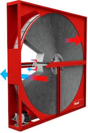
Regenerative heat exchangers of own design The regenerative heat exchanger was first used as an Air Preheater in steam boiler plants, where combustion air was heated up by the hot flue gases. Since 1976 this type of heaters has also been applied in Flue Gas Desulphurization (FGD) and Tail-end Selective Catalytic Reduction (SCR) plants as Gas-Gas Heaters for exchange of heat between untreated and treated flue gases.
The working principle of a regenerative heat exchanger is a slowly rotating rotor filled with heating elements which transfer heat between two or more gas flows. The hot gas flow to be cooled down has to be in counterflow with the cold gas flow to be heated up. Rotor diameters range from 5 to 25 meters and the heaviest rotor weighs more than 1600 tons.
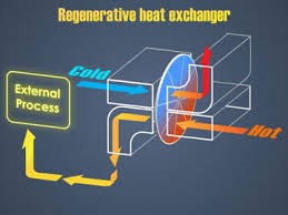
A regenerative heat exchanger, or more commonly a regenerator, is a type of heat exchanger where heat from the hot fluid is intermittently stored in a thermal storage medium before it is transferred to the cold fluid. To accomplish this the hot fluid is brought into contact with the heat storage medium, then the fluid is displaced with the cold fluid, which absorbs the heat.
In regenerative heat exchangers, the fluid on either side of the heat exchanger can be the same fluid. The fluid may go through an external processing step, and then it is flowed back through the heat exchanger in the opposite direction for further processing. Usually, the application will use this process cyclically or repetitively.
Regenerative heating was one of the most important technologies developed during the Industrial Revolution when it was used in the hot blast process on blast furnace, It was later used in glass and steel making, to increase the efficiency of open hearth furnaces, and in high pressure boilers and chemical and other applications, where it continues to be important today.
The first regenerator was invented by Rev. Robert Stirling in 1816 and is commonly found as a component of his Stirling engine. The simplest Stirlings, and most models use a less efficient but simpler to construct, displacer instead.
Later applications included the blast furnace process known as hot blast and the Open hearth furnace also called Siemens regenerative furnace (which was used for making glass), where the hot exhaust gases from combustion are passed through firebrick regenerative chambers, which are thus heated. The flow is then reversed so that the heated bricks preheat the fuel.
Edward Alfred Cowper applied the regeneration principle to blast furnaces, in the form of the “Cowper stove”, patented in 1857.[4] This is almost invariably used with blast furnaces to this day
TYPES OF REGENERATORS:
In rotary regenerators, the matrix rotates continuously through two counter-flowing streams of fluid. In this way, the two streams are mostly separated but the seals are generally not perfect. Only one stream flows through each section of the matrix at a time; however, over the course of a rotation, both streams eventually flow through all sections of the matrix in succession. Each portion of the matrix will be nearly isothermal since the rotation is perpendicular to both the temperature gradient and flow direction, and not through them. The two fluid streams flow counter-current. The fluid temperatures vary across the flow area; however, the local stream temperatures are not a function of time.
In a fixed matrix regenerator, a single fluid stream has cyclical, reversible flow; it is said to flow “counter-current”. This regenerator may be part of a valveless system, such as a Stirling engine. In another configuration, the fluid is ducted through valves to different matrices in alternate operating periods Ph and Pc resulting in outlet temperatures that vary with time.
Another type of regenerator is called a micro scale regenerative heat exchanger. It has a multilayer grating structure in which each layer is offset from the adjacent layer by half a cell which has an opening along both axes perpendicular to the flow axis. Each layer is a composite structure of two sublayers, one of a high thermal conductivity material and another of a low thermal conductivity material. When a hot fluid flows through the cell, heat from the fluid is transferred to the cell walls and stored there. When the fluid flow reverses direction, heat is transferred from the cell walls back to the fluid.
The third type of regenerator is called a “Rothemuhle” regenerator. This type has a fixed matrix in a disk shape, and streams of fluid are ducted through rotating hoods. The Rothemuhle regenerator is used as an air preheater in some power generating plants. The thermal design of this regenerator is the same as of other types of regenerators.
ADVANTAGES OF REGENERATORS:
The advantages of a regenerator over a recuperating (counter-flowing) heat exchanger is that it has a much higher surface area for a given volume, which provides a reduced exchanger volume for a given energy density, effectiveness and pressure drop. This makes a regenerator more economical in terms of materials and manufacturing, compared to an equivalent recuperator.
The design of inlet and outlet headers used to distribute hot and cold fluids in the matrix is much simpler in counterflow regenerators than recuperators. The reason behind this is that both streams flow in different sections for a rotary regenerator and one fluid enters and leaves one matrix at a time in a fixed-matrix regenerator.
Furthermore, flow sectors for hot and cold fluids in rotary regenerators can be designed to optimize pressure drop in the fluids. The matrix surfaces of regenerators also have self-cleaning characteristics, reducing fluid-side fouling and corrosion.
Finally, properties such as small surface density and counter-flow arrangement of regenerators make it ideal for gas-gas heat exchange applications requiring effectiveness exceeding 85%. The heat transfer coefficient is much lower for gases than for liquids, thus the enormous surface area in a regenerator greatly increases heat transfer.
DISADVANTAGES OF REGENERATION:
The major disadvantage of a regenerator is that there is always some mixture of the fluid streams, and they can not be completely separated. There is an unavoidable carryover of a small fraction of one fluid stream into the other.
In the rotary regenerator, the carryover fluid is trapped inside the radial seal and in the matrix, and in a fixed-matrix regenerator, the carryover fluid is the fluid that remains in the void volume of the matrix.
This small fraction will mix with the other stream in the following half-cycle. Therefore, regenerators are only used when it is acceptable for the two fluid streams to be mixed.
Mixed flow is common for gas-to-gas heat and/or energy transfer applications, and less common in liquid or phase-changing fluids since fluid contamination is often prohibited with liquid flows.
The constant heating and cooling that takes place in regenerative heat exchangers put a lot of stress on the components of the heat exchanger, which can cause cracking or breakdown of materials.
4. SHELL AND TUBE HEAT EXCHANGER
4.1 PURPOSE OF HEAT EXCHANGER
The purpose of a heat exchanger is just that–to exchange heat. Most processes require the heating or cooling of streams to produce the desired temperature before the stream can be fed to operations. In any heat exchanger, there must be a fluid that requires a change in energy (heating or cooling) and fluid that can provide that energy change.
One fluid is sent through a pipe on the inside of the heat exchanger while the other fluid is sent through a pipe on the outside. In this configuration, no mixing of the hot and cold fluids needs to take place. This is very convenient for many processes, especially when product purity needs to be ensured. This arrangement also allows for large quantities of heat to be transferred quickly, and it is relatively easy to maintain consistent operating conditions.
There are three principal means of achieving heat transfer, conduction, convection, and radiation. Heat exchangers run on the principles of convective and conductive heat transfer. Radiation does occur in any process. However, in most heat exchangers the amount of contribution from radiation is minuscule in comparison to that of convection and conduction. Conduction occurs as the heat from the hot fluid passes through the inner pipe wall. To maximize heat transfer, the inner-pipe wall should be thin and very conductive. However, the biggest contribution to heat transfer is made through convection.
There are two forms of convection; these are natural and forced convection. Natural convection is based on the driving force of density, which is a slight function of temperature. As the temperature of most fluids is increased, the density decreases slightly. Hot fluids, therefore, have a tendency to rise, displacing the colder fluid surrounding it. This creates the natural “convection currents” which drive everything from the weather to boiling water on the stove. Forced convection uses a driving force based on an outside source such as gravity, pumps, or fans. Forced convection is much more efficient, as forced convection flows are often turbulent. Turbulent flows undergo a great deal of mixing which allows the heat to be transferred more quickly.
In this particular apparatus, water is used as both the hot and cold fluid. The purpose of this heat exchanger is to cool a hot stream. Cooling water flows through the outer pipe (the shell), and hot water flows through the inner pipe (actually 28 tubes) on the inside. Heat transfer occurs in both directions; the hot water is cooled, and the cooling water is heated. This arrangement is called a “shell-and-tube” heat exchanger. There are many other forms of heat exchangers; most notably, the double-pipe heat exchanger.
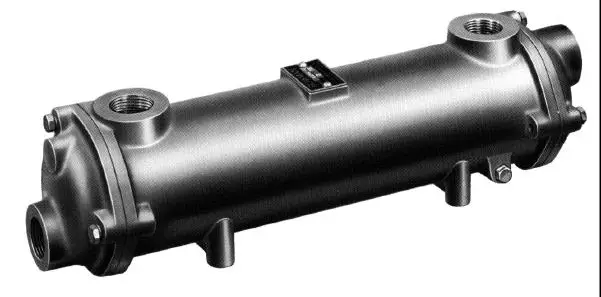
In this arrangement, a cold fluid flows through a pipe in the centre of the apparatus and is heated by a hot fluid on the outside of that pipe. The hot water used in the shell-and-tube heat exchanger is produced by means of a double-pipe heat exchanger. The discharge from the shell of the shell-and-tube heat exchanger is circulated through the inner pipe of the double pipe heat exchanger. Low-pressure steam condenses on the outside of the pipe, heating the water before it enters the tubes of the shell-and-tube heat exchanger.
A laboratory manual was created for the shell-and-tube heat exchanger. The theories of heat transfer and heat exchangers were explained and followed by literature correlations. All of the instrument specifications were defined. A procedure for the use and safety of the equipment was outlined. Measurements taken by our group during calibration of the flow meters were included. This was followed by sample calculations of the Reynolds numbers and error analysis for those calculations. This manual is sufficient to teach anyone how to run the shell-and-tube heat exchanger.
It is recommended that this laboratory manual be filed with Bob Cox in MEB 3520. Since this manual has been written, there is no longer a need to have students attempting to find instrument specifications and learn the equipment on their own. Students should be given access to this information to aid them in their own research projects, however, it is important that they not use this information as the basis for their laboratory reports.
4.2 THEORY
The theory behind the operation of a shell-and-tube heat exchanger involves the consideration of both convective and conductive heat transfer. The treatment presented in this report is based on the work done by Incropera and Dewitt (1996).
The determination of the overall heat transfer coefficient is one of the most important, and often most uncertain, quantities in the analysis of heat exchangers. This coefficient primarily accounts for all of the conductive and convective resistances (k and h, respectively) between fluids separated by a wall (or tube), and further takes into account thermal resistances caused by fouling on the wall (i.e., rust, scaling, etc.) by means of fouling factors on both sides. For an unfinned, tubular heat exchanger the overall heat transfer coefficient, Ud, can be expressed as

Another important quantity in heat exchanger analysis is the total rate of heat transfer between the hot and cold fluid. Several different expressions for this heat transfer rate can be developed, relating the heat transfer rate to quantities such as the inlet and outlet fluid temperatures and the overall heat transfer coefficient. When these expressions are developed, care must be taken to ensure that the appropriate mean temperature expressions are used. Several assumptions can be made to simplify these expressions. In this case, we assume: negligible heat transfer between the system and its surroundings, negligible potential or kinetic energy changes, constant specific heats, and that the fluids are not undergoing any phase change. In this case, the total heat transfer rate, q, becomes
where
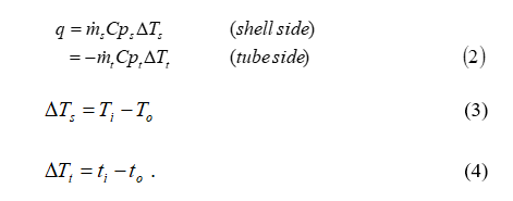
When the total heat transfer rate is related to the overall heat transfer coefficient, another expression develops. This time

where A is the area for heat transfer, F is the correction factor for flow, and DTLM is the log mean temperature difference between the inlet and outlet temperatures. In a shell-and-tube heat exchanger, the area for heat transfer is

The correction factor, F, is needed due to the fact the theory was originally developed for the case of pure counterflow. In a shell-and-tube heat exchanger, there is usually one shell pass and some multiple of two tube passes. The shell-and-tube heat exchanger used in experimentation has one shell pass and two tube passes. For this case, the correction factor, F, becomes
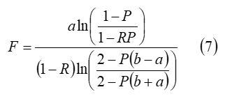
where the equations for each of the variables in the equation are
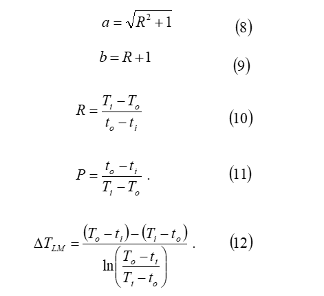
Finally, the log means temperature difference is defined as the mean between the inlet and outlet temperatures for both the shell-and-tube. The equation for the log mean temperature difference is
Another important consideration in the development of the theory behind a heat exchanger is the Reynolds number, a ratio between the inertial and viscous forces in flow. The value of this dimensionless group denotes whether the flow in the heat exchanger is laminar or turbulent. Naturally, turbulent flow is preferred, like heat transfer in turbulent flow is much greater. The Reynolds number for flow through tubes is given by

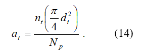
with at, the tube flow area, given by
The Reynolds number for flow through the shell is quite a complicated expression due to the number of tubes and baffles the flow encounters and the pitch of tubes. The shell Reynolds number can be written as

where the quantity De represents the equivalent shell diameter and is given by

The quantity Vs represents the velocity of the flow and is given by

whereas represents the shell flow area and is given by
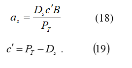
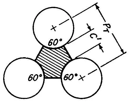
and c’ is a quantity called the shell clearance, which is
PT is a quantity referred to as the “pitch” of the tubes. The pitch describes the spacing of the tubes inside the heat exchanger and their alignment in relation to each other. The pitch of the tubes inside of the shell-and-tube heat exchanger used in experimentation is triangular and is best described in Figure 4.2(a).
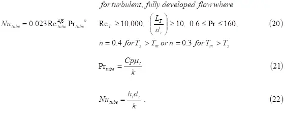
Several correlations are used to determine values for the variables that, along with instrument specifications, yield enough data to calculate Ud. These correlations are dependent on the value of the Reynolds number. Using the equations described above, Reynolds numbers were calculated for both the shell-and-tube side flows. Both were found to be turbulent at the maximum flow rate. The Reynolds number inside the tubes at maximum flow was over 10,000 and all of the other conditions likewise held, allowing the use of the following correlation:
and
Therefore, Equations 20-22 allow the determination of hi.
Thermal conductivity, k, can be looked up in a handbook once an approximate temperature is determined. Ud can be calculated by relating Equation 2 for the tube side with Equation 5. Equation 2 is selected based on the fact that heat loss to ambient air occurs on the shell side. Also, the fouling factors Rfo and RFI can be looked up from various sources, including Standards of the Tubular Exchanger Manufacturers Association, or lumped together and determined experimentally. This allows Equation 1 to be solved for ho, the shell side heat transfer coefficient. This value can be compared to literature values obtained from empirical equations found in Kern’s (1990) work:
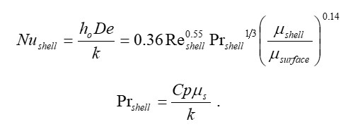
and
Some of the very basic components of a shell and tube type heat exchangers are as given below:
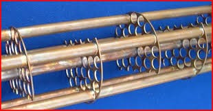
Tubes:
The tubes are the basic components of a shell and tube type heat exchanger. The outer surfaces of the tubes are the boundary along which heat transfer takes place.
It is therefore recommended that the tubes materials should be highly thermal conductive otherwise proper heat transfer will not occur. The tubes of Copper, Aluminium and other thermally conductive materials are commonly used in practice.
Tube sheets:
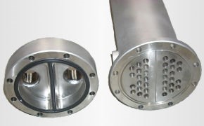
The tubes are held in place by being inserted into holes in the tube sheet and there either expanded into grooves cut into the holes or welded to the tube sheet where the tube protrudes from the surface. The tube sheet is usually a single round plate of metal that has been suitably drilled and grooved to take the tubes (in the desired pattern), the gaskets, the spacer rods and the bolt circle where it is fastened to the shell. However, where mixing between the two fluids (in the event of leaks where the tube is sealed into the tube sheet) must be avoided, a double tube sheet may be provided.
Shell:
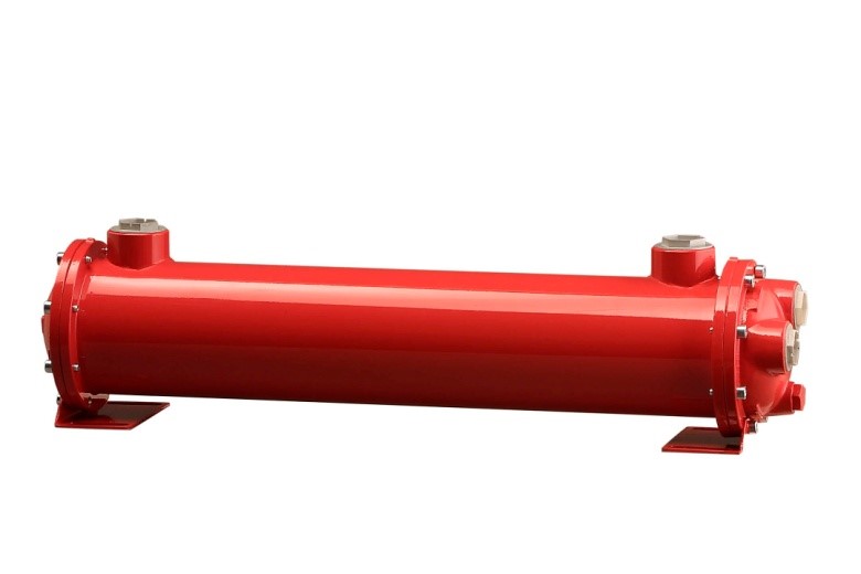
The shell is simply the container for the shell side fluid, and the nozzles are the inlet and exit ports. The shell normally has a circular cross-section and is commonly made by rolling a metal plate of the appropriate dimensions into a cylinder and welding the longitudinal joint (“rolled shells”)
Channel covers:
The channel covers are round plates that bolt to the channel flanges and can be removed for the tube inspection without disturbing the tube side piping.
In smaller heat exchangers, bonnets with flanged nozzles or threaded connections for the tube side piping are often used instead of the channel and channel covers.
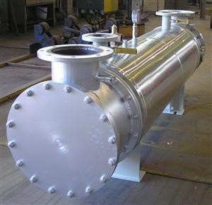
Baffles:
Baffles serve two functions; Most importantly, they support the tubes in the proper position during assembly and operation and prevent vibration of the tubes caused by flow-induced eddies, and secondly, they guide the shell side flow back and forth across the tube field, increasing the velocity and heat transfer coefficient
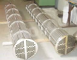
Baffle spacing:
Baffle spacing is the centerline-to-centerline distance between adjacent baffles. It is the most vital parameter in THE design. The TEMA standards specify the minimum baffle spacing as one-fifth of the shell inside diameter or 2 in., whichever is greater. Closer spacing will result in poor bundle penetration by the shell side fluid and difficulty in mechanically cleaning the outsides of the tubes. Furthermore, a low baffle spacing results in a poor stream distribution as will be explained later.
The
maximum baffle spacing is the shell inside diameter. Higher baffle spacing will
lead to predominantly longitudinal flow, which is less efficient than
cross-flow, and large unsupported tube spans, which will make the exchanger
prone to tube failure due to flow-induced vibration. Optimum baffles pacing.
For turbulent flow on the shell side (Re > 1,000), the heat-transfer
coefficient varies to the 0.6–0.7 power of velocity; however, pressure drop varies
to the 1.7–2.0 power. For laminar flow (Re < 100), the exponents are 0.33
for the heat transfer coefficient and 1.0 for pressure drop. Thus, as baffle
spacing is reduced, pressure drop increases at a much faster rate than does the
heat-transfer coefficient. This means that there will be an optimum ratio of
baffle spacing to shell inside diameter that will result in the highest
efficiency of conversion of pressure drop to heat transfer. This optimum ratio
is normally between 0.3 and 0.6
4.3 WORKING PROCEDURE:
The shell-and-tube heat exchanger used in experimentation is located in MEB 3520. Figure 2 describes the setup of this shell-and-tube heat exchanger. Water from the shell is used to fill the tank and is then pumped to the double-pipe heat exchanger where it is heated with low-pressure steam.
Upon leaving the double-pipe heat exchanger, the water travels through the tubes of the shell-and-tube heat exchanger, where it is cooled and returned to the tank. On Figure 2, numbers one and two represent gate valves on the steam line entrance and exit of the double-pipe heat exchanger. Valves three and nine are ball valves that can be used to manually control the flow through the tubes and the shell. Valves five and seven are referred to as computer controlled valves. The Opto-22 software is connected to manual valve actuators, which open and close the valves to various percentages.
Valve five controls the tube flow, while valve seven controls the shell flow. The gate valve represented by valve six is, in reality, two gate valves that can be used in conjunction to direct the flow either from the pump directly back to the tank or from the pump through the double-pipe heat exchanger.
Number ten represents the gate valve that controls the flow of building water through the shell. Numbers four and eight show the position of the flow meters, which are also connected to the Opto-22 software.
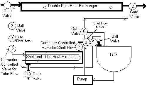
Figure 3 is a diagram of the shell-and-tube heat exchanger only. It shows key points of interest in more detail than Figure 2 and shows the position of the thermocouples for both The disk included with this manual includes this picture, as well as pictures of the individual valves, thermocouples, and other pieces of equipment. While reviewing the works of renowned scholars it has been seen that a significant amount of works has been done in fields of shell and tube type heat exchangers (STHE).
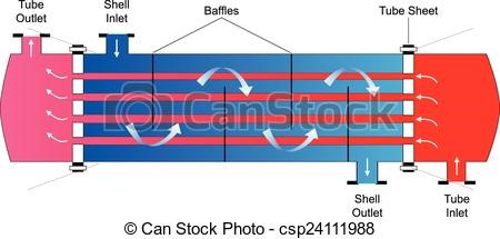
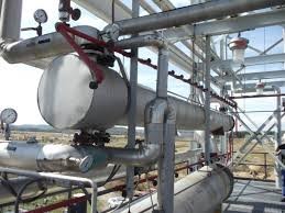
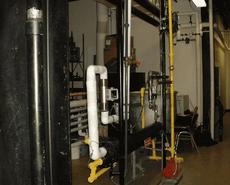
Shell and tube heat exchanger Types:
There can be many variations on the shell and tube design. Typically, the ends of each tube are connected to plenums (sometimes called water boxes) through holes in tube sheets. The tubes may be straight or bent in the shape of a U, called U-tubes.
U-Tubes
The Shell and Tube (u-tube) is the most common type of heat exchanger used in the process, petroleum, chemical and HVAC industries, it contains a number of parallel u-tubes inside a shell. Shell Tube heat exchangers are used when a process requires large amounts of fluid to be heated or cooled. Due to their design, shell tube heat exchangers offer a large heat transfer area and provide high heat transfer efficiency.
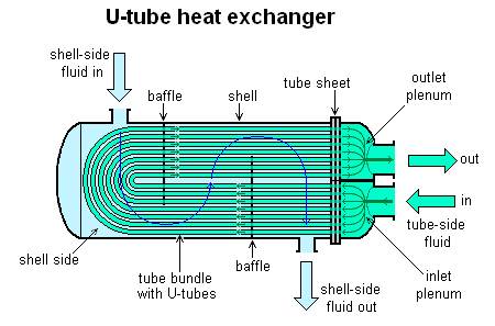
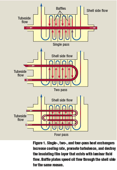
In nuclear power plants called pressurized water reactors, large heat exchangers called steam generators are two-phase, shell-and-tube heat exchangers which typically have U-tubes. They are used to boil water recycled from a surface condenser into steam to drive the turbine to produce power. Most shell-and-tube heat exchangers are either 1, 2, or 4 pass designs on the tube side. This refers to the number of times the fluid in the tubes passes through the fluid in the shell. In a single pass heat exchanger, the fluid goes in one end of each tube and out the other.
Surface condensers in power plants are often 1-pass straight-tube heat exchangers. Two and four pass designs are common because the fluid can enter and exit on the same side. This makes construction much simpler.
Straight-Tube 1-pass
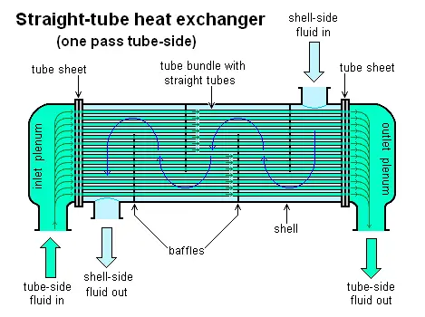
One pass means that the fluid enter on one side and exit on the other side of the heat exchanger
There are often baffles directing flow through the shell side so the fluid does not take a short cut through the shell side leaving ineffective low flow volumes.
Countercurrent heat exchangers are most efficient because they allow the highest log mean temperature difference between the hot and cold streams.
Many companies, however, do not use single pass heat exchangers because they can break easily in addition to being more expensive to build. Often multiple heat exchangers can be used to simulate the countercurrent flow of a single large exchanger.
The diagram at the right shows a schematic diagram of a straight tube, shell and tube heat exchanger and the diagram on the left shows a tube bundle for a straight tube heat exchanger. A straight tube heat exchanger is easier to clean than a U-tube heat exchanger, so it is better for a tube side fluid that tends to foul the tube, causing a need for regular cleaning. The U-tube heat exchanger works well if the two fluids have greatly different thermal expansion characteristics because it can allow the tube and the shell to expand or contract independently.
Straight-Tube 2-pass:
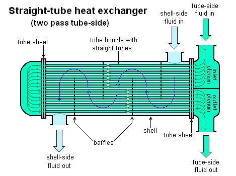
Two pass heat exchanger means that the fluid enters and exit on the same side of the heat exchanger.
There are many different types or designs of shell and tube heat exchangers to meet various process requirements. Shell and Tube heat exchangers can provide steady heat transfer by utilizing multiple passes of one or both fluids. SEC shell and tube heat exchangers come in two (2) and four (4) pass models standard, and multi-pass custom models.
Selection of tube material:-
To be able to transfer heat well, the tube material should have good thermal conductivity. Because heat is transferred from a hot to a cold side through the tubes, there is a temperature difference through the width of the tubes. Because of the tendency of the tube material to thermally expand differently at various temperatures, thermal stresses occur during operation. This is in addition to any stress from high pressures from the fluids themselves. The tube material also should be compatible with both the shell and tube side fluids for long periods under the operating conditions (temperatures, pressures, pH, etc.) to minimize deterioration such as corrosion. All of these requirements call for careful selection of strong, thermally-conductive, corrosion-resistant, high-quality tube materials, typically metals. Poor choice of tube material could result in a leak through a tube between the shell and tube sides causing fluid cross-contamination and possibly loss of pressure.
Standard heat exchangers particularly made for heavy duty ever with medium pressure ranges. The composition can be made with a different choice of materials, all sort of combinations make this type of exchangers versatile enough to solve any problem of fluids, flows, even with high duty rating.
Baffles:
Punched from steel plates, with supporting lips for higher thermal efficiency and more safety in case of vibration.
Shell &Tubesheets:
Welded carbon steel construction, to give most rugged exchanger, adequate thickness for t trouble free long life. Shell side connections made also for customers requirement, over the standard threaded connections we propose flanges
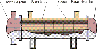
The shell and tube exchanger consists of four major parts:
Front Header—this is where the fluid enters the tube side of the exchanger. It is sometimes referred to as the Stationary Header.
Rear Header—this is where the tube side fluid leaves the exchanger or where it is returned to the front header in exchangers with multiple tube side passes.
Tube bundle—this comprises of the tubes, tube sheets, baffles and tie rods etc. to hold the bundle together.
4.4 ADVANTAGES AND DISADVANTAGES
ADVANTAGES
- Less expensive as compared to Plate type coolers
- Can be used in systems with higher operating temperatures and pressures
- The pressure drop across a tube cooler is less
- Tube leaks are easily located and plugged since pressure test is comparatively easy
- Tubular coolers in the refrigeration system can act as a receiver also.
- Using sacrificial anodes protects the whole cooling system against corrosion
- Tube coolers may be preferred for lubricating oil cooling because of the pressure differential
DISADVANTAGES
Heat transfer efficiency is less compared to plate type cooler
- Cleaning and maintenance is difficult since a tube cooler requires enough clearance at one end to remove the tube nest
- The capacity of tube cooler cannot be increased.
- Requires more space in comparison to plate coolers
4.5 APPLICATIONS
The simple design of a shell and tube heat exchanger makes it an ideal cooling solution for a wide variety of applications. One of the most common applications is the cooling of hydraulic fluid and oil in engines, transmissions and hydraulic power packs.
With the right choice of materials, they can also be used to cool or heat other mediums, such as swimming pool water or charge air. One of the big advantages of using a shell and tube heat exchanger is that they are often easy to service, particularly with models where a floating tube bundle (where the tube plates are not welded to the outer shell) is available.
Generally, the shell and heat type heat exchanger is widely used for various purposes having limitation to be designed for maximum up to 15000 psi, 1000°F & 30000 ft2 /shell. Beyond the above-given parameter, special consideration is required for the design of heat exchanger. The design is ideal for high pressure and temperature services. Shell and tube heat exchanger is easy to clean for floating head type configuration so, can be used in dirty services. Shell and tube type heat exchanger can be used for higher temperature difference services as it can accommodate thermal expansion. They are most suitable for gas services and phase change service. They can be designed for special operating conditions: vibration, heavy fouling, highly viscous fluids, erosion, corrosion, toxicity, radioactivity, multicomponent mixtures, and so on. They are the most versatile exchangers, made from a variety of metal and nonmetal materials (such as graphite, glass, and Teflon) and range in size from small [0.1m2 (1 ft2 )] to supergiant [over 105m2 (106 ft2 )] surface area. They are used extensively as process heat exchangers in the petroleum-refining and chemical industries; as steam generators, condensers, boiler feed water heaters and oil coolers in power plants; as condensers and evaporators in some air-conditioning and refrigeration applications; in waste heat recovery applications with heat recovery from liquids and condensing fluids; and in environmental control.
CONCLUSION
On the basis of the above study, it is clear that a lot of factors affect the performance of the heat exchanger and the optimization obtained by the formulas depicts the cumulative effect of all the factors over the performance of the heat exchanger. It is observed that by changing the value of one variable by keeping the rest variable as constant we can obtain the different results. Based on that result we can optimize the design of the shell and tube type heat exchanger. Higher the thermal conductivity of the tube metallurgy higher the heat transfer rate will be achieved. Less is the baffle spacing, more is the shell side passes, higher the heat transfer but at the cost of the pressure drop. So, while optimization it must be taken care that the advantage in one of the output parameter can affect the other parameters, which can lead to an increase in initial or operating cost.
After the above discussion, it is easy to say that the shell & tube type heat exchangers have been given great respect among all the classes of heat exchangers due to their virtues like comparatively large ratios of heat transfer area to volume and weight and many more. Moreover well designed as well as described methods are available for its designing and analysis. The literature survey also shows the importance of this class of heat exchangers.
REFERENCE
- A Gopichand, Prof.A.V.N.L. Sharma, G. Vijay Kumar, A. Srividya, “Thermal analysis of shell and tube type heat exchanger using MATLAB and FLOEFD software. ”, Volume 1 Issue :3, ,pp 279-281.
- A.O. Adelaja, S.J. Ojolo and M.G. Sobamowo, “Computer Aided Analysis of Thermal and Mechanical Design of Shell and Tube Heat Exchangers”, Advanced Materials Vol. 367 (2012), pp731-737, Trans Tech Publications Switzerland.
- B Jayachandriah1, K. Rajsekhar, “Thermal Computer-Aided Analysis of Thermal and Mechanical design of shell and tube exchangers,” Advanced Materials vol. 367(2012) pp 731-73, Trans Tech publications, Switzerland.
- Dutta B.K. “Heat Transfer-Principles and Applications”, PHI Pvt. Ltd., New Delhi, 1st ed. 2006.
- D. Q. Kern, “Process Heat Transfer”, McGraw-Hill Book Company, Int. ed. 1965.
- Ebieto, C.E. and Eke G.B., “Performance Analysis of Shell and Tube Heat Exchangers using Miscible System: A case study”, Journal of Emerging Trends in Engineering and Applied Sciences,2012 3 (5), pp. 899- 903.al
- Indian Standard (IS: 4503-1967): Specification for Shell and Tube Type Heat Exchangers, BIS 2007, New Delhi.
- Rajagopal Thundil Karuppa Raj, Srikanth Ganne, “Shell side numerical analysis of a shell and tube heat exchanger considering the effect of baffle inclination angle on a fluid flow”, Thundil Karuppa Raj, R., et al: Shell side numerical analysis of shell and tube heat exchangers, Thermal science: Year 2012, Vol.16, No.4, pp 1165-1174.
- R. K. Sinnott, Coulson & Richardson‟s Chemical Engineering: “Chemical Engineering Design” (volume), Butterworth-Heinemann, 3rd ed. 1999. [10]S. Noie Baghban, M. Moghiman and E. Salehi, “Thermal Analysis of shell side flow of shell and tube type heat exchanger using experimental and theoretical methods ”, Institute for Scientific Research, University of Guanajuato Lascurain de Retana No. 5, 36000 Guanajuato, Gto, México.

HI, it was nice information related to the Shell and tube heat exchangers. Thanks for sharing such valuable information. I really liked it.