Shear force and Bending moment diagram in beams can be useful to determine the maximum absolute value of the shear force and the bending moment of the beams with respect to the relative load. Before we are drawing the Shear force and Bending moment diagram, we must know different type of beams and different type of loads, reaction forces acting on them.
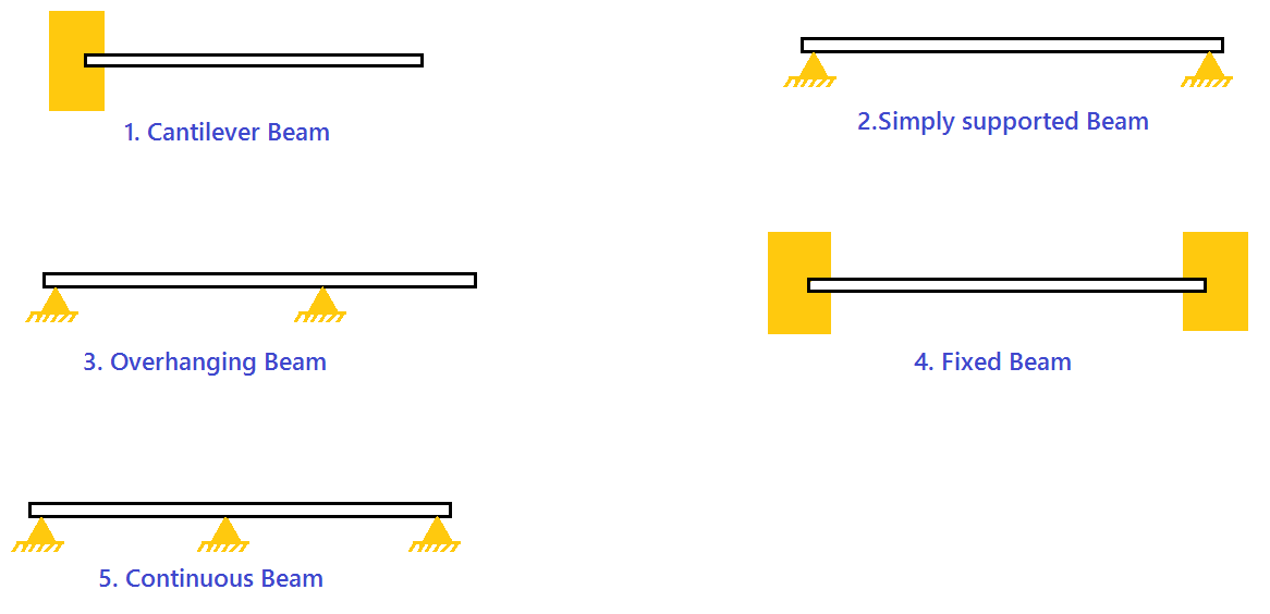
Type of Beams
- Cantilever Beam
- Simply Supported Beam
- Overhanging Beam
- Fixed Beam
- Continuous Beam
Type of Loads
A beam is usually horizontal, and the applied load is vertical.
- Concentrated or Point Load: Act at a point.
- Uniformly Distributed Load: Load spread along the length of the Beam.
- Uniformly Varying Load: Load spread along the length of the Beam, Rate of varying loading point to point.

Sign conversion for Shear force and Bending moment
For a simply supported beam, If a point load is acting at the centre of the beam. Imagine a section X-X divide the beam into two portions. See the pic below.
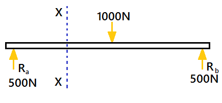
A simply supported beam is carrying a load (point load) of 1000N at its middle point. The reactions support will be equal to 500N(Ra=Rb). The section X-X make the beam into two parts.
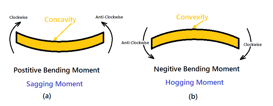
The moment of all the forces, i.e., load and reaction to the left of section X-X is Clockwise
The moment of all the forces, i.e., load and reaction to the right of section X-X are Anti-Clockwise.
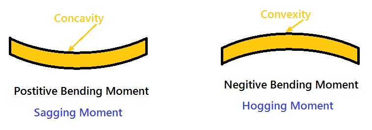
So this makes the beam a Sagging moment(Concavity). Here the bending moment is Positive. See (a)
If the left portion makes an anticlockwise moment and the right portion of the section makes a Clockwise moment, then it is hogging moment. Bending moment Negative.
Similarly for Shear force is positive when the left portion of the section goes upwards or the right portion of the section goes downwards.
Shear force is Negative when left portion of the section goes downwards, or the right portion of the section goes upwards.
Here some of the points are very important to consider while drawing the SFD and BMD. They listed below.
Steps to draw Shear force and Bending moment diagrams
In SFD and BMD diagrams Shear force or Bending moment represents the ordinates, and the Length of the beam represents the abscissa.
- Consider the left or the right portion of the section.
- Add the forces(including reactions) normal to the beam on the one of the portion.
- If the right portion of the section is chosen, then the force acting downwards is positive and the force acting upwards is negative.
- If the Left portion of the section is chosen, then the force acting downwards is negative and the force acting upwards is positive.
- The positive values of Shear force and Bending moment are plotted above the baseline the negative values are plotted below the baseline.
- Shear force diagram will increase or decrease suddenly. I.e., By vertical straight line at a section where there is a vertical point load.
- Shear force between any two vertical loads will be constant. And hence the shear force between the two vertical loads will be horizontal.
- The bending moment at the two ends of the simply supported beam and at the free end of a cantilever will be zero.
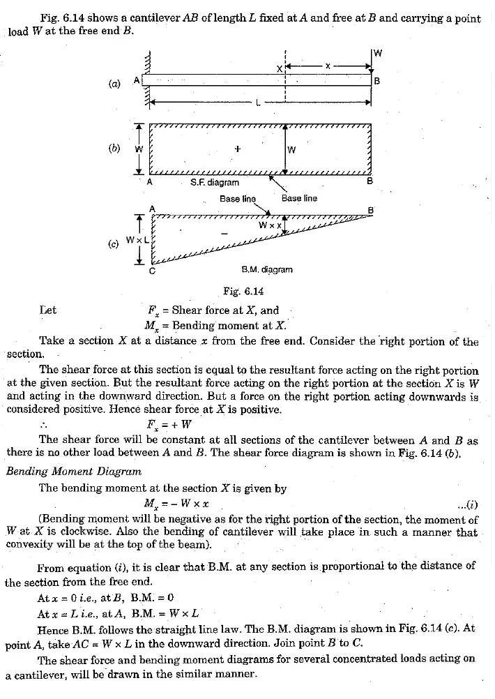
Shear force and Bending moment Diagram for a Cantilever beam with a Point load at the free end
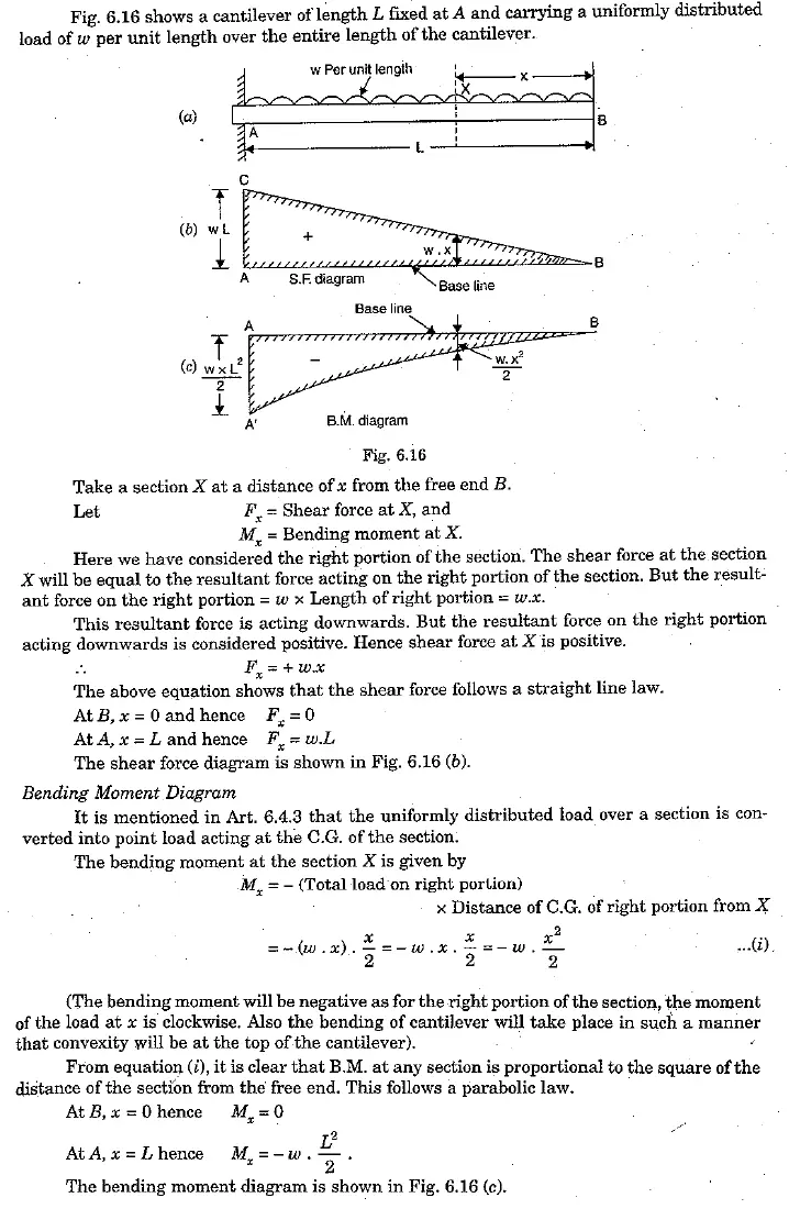
Shear force and Bending moment Diagram for a Cantilever beam with a Uniformly distributed load
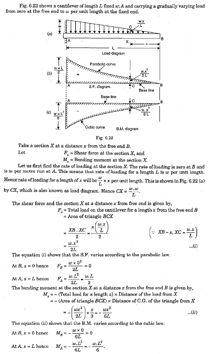
SFD and BMD for a Cantilever beam with a Uniformly varying load.

Leave a Reply