A final Year project on the Residual stress analysis of super duplex stainless steel welded joint using XRD (X-ray Diffraction) submitted by Prasad .K to extrudesign.com.
ABSTRACT
Welding is the process of joining two or more similar or dissimilar metals and finds a wide range of industrial applications in aerospace, marine, structural etc. During welding, residual stresses are formed because of differential contractions which occur, as the weld metal solidifies and cools to ambient temperature. Residual stresses have severe effect in the welded joints as they decrease the lifespan and the properties of the material.
This research deals with residual stress analysis of welded joints for UNS S32760 super duplex stainless steel material. In order to analyze the effect of residual stresses, 8 welded Butt joints of super duplex stainless steel are made using TIG and MIG Welding methods and X-ray diffraction (XRD) is performed on the joints. The scope of the project also includes an investigation on how to relieve the residual stresses induced in the welded joints by following different approaches. One of the methods is to provide peening. Different peening methods are analyzed and the appropriate one is selected. A further effect of residual stresses on the mechanical properties of the welded joints was also analyzed before peening and after peening.
The hardness of the specimens (welded joints) is improved by relieving residual stresses using hammer peening.
Topics: Residual Stress analysis, Residual Stress analysis of a welded joint using the XRD
1. INTRODUCTION
Welding is the process of joining two similar or dissimilar metallic components with the application of heat, with or without the application of pressure and with or without the use of filler metal. Heat may be obtained by chemical reaction, electric arc, electrical resistance, frictional heat, sound and light energy. If no filter metal is used during welding then it is termed as ‘Autogenous Welding Process. Welding plays a major role in the construction of transport tankers for transporting oil, water, milk and fabrication of welded tubes and pipes, chains, LPG cylinders and other items. Steel furniture, gates, doors and door frames, body and other parts of white goods items such as refrigerators, washing machines, microwave ovens and many other items of general applications are fabricated by welding. Some of the applications of welded joints are shown below.
1.1 Applications of Welded joints
Pressure Vessels
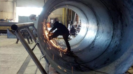
One of the first major use of welding was in the fabrication of pressure vessels. Welding made considerable increases in the operating temperatures and pressures possible as compared to riveted pressure vessels.
Bridges
Early use of welding in bridge construction took place in Australia. This was due to problems in transporting complete riveted spans or heavy riveting machines necessary for fabrication on-site to remote areas. The first all-welded bridge was erected in the UK in 1934. Since then all welded bridges are erected very commonly and successfully.
Ship Building
Ships were produced earlier by riveting. Over ten million rivets were used in ‘Queen Mary’ ship which required skills and massive organization for riveting but welding would have allowed the semiskilled/unskilled labour and the principle of pre-fabrication. Welding found its place in shipbuilding around 1920 and presently all-welded ships are widely used. Similarly, submarines are also produced by welding.
Building Structures
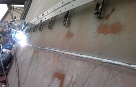
Arc welding is used for the construction of steel building leading to considerable savings in steel and money. In addition to the building, huge structures such as steel towers etc also require welding for fabrication.
Aircraft and Spacecraft:
Similar to ships, aircraft were produced by riveting in early days but with the introduction of jet engines welding is widely used for aircraft structure and for joining of skin sheet to the body. Space vehicles which have to encounter frictional heat, as well as low temperatures, require outer skin and other parts of special materials. These materials are welded with full success achieving safety and reliability.

Railways
Railways use welding extensively for the fabrication of coaches and wagons, wheel tyres laying of new railway tracks by mobile flash butt welding machines and repair of cracked/damaged tracks by thermit welding.
Automobiles
Production of automobile components like chassis, body and its structure, fuel tanks and joining of door hinges require welding.
Electrical Industry
Starting from generation to distribution and utilization of electrical energy, welding plays an important role. Components of both hydro and steam power generation system, such as penstocks, water control gates, condensers, electrical transmission towers and distribution system equipment are fabricated by welding. Turbine blades and cooling fins are also joined by welding.
Electronic Industry
Electronic industry uses welding to a limited extent such as for joining leads of special transistors but other joining processes such as brazing and soldering are widely being used. Soldering is used for joining electronic components to printed circuit boards. Robotic soldering is very common for joining of parts to printed circuit boards of computers, television, communication equipment and other control equipment etc.
Nuclear Installations
Spheres for the nuclear reactor, pipeline bends joining two pipes carrying heavy water and other components require welding for safe and reliable operations.
Defense Industry
Defence industry requires welding for joining of many components of war equipment. Tank bodies fabrication, joining of turret mounting to the main body of tanks are typical examples of applications of welding.
Micro-Joining
It employs the processes such as micro-plasma, ultrasonic, laser and electron beam welding, for joining of thin wire to wire, foil to foil and foil to wire, such as producing junctions of thermocouples, strain gauges to wire leads etc.
Apart from above applications welding is also used for joining of pipes, during the laying of crude oil and gas pipelines, construction of tankers for their storage and transportation. Offshore structures, dockyards, loading and unloading cranes are also produced by welding.
1.2 IMPORTANCE OF WELDED JOINTS
Welding plays an important role as they provide adequate strength to the joints. But during the process of welding, residual stresses are formed within the joint sand they affect the Mechanical properties of the welded joints. Welding done in an organized way will provide leak-proof joints
Suppose the purpose is to join the plates in butt joint configuration, at this point riveted joint, bolted joint is of no use, even if you joined them backing strap is required and still required strength will not be there, at this stage welding is the optimal way for joining. Proper welding joint provides strength more than the base material.
Some more Applications of welded joints
- Aerospace engineering
- Train and rail carriages
- Automotive industry and auto suppliers
- Electricals and electronics
- Domestic hardware
- Radiators and containers
- Medical instruments and supplies
- Nuclear equipment
- Food and beverage industry
1.3 Residual Stresses in welded joints
Residual stress is the stress that exists within a material without application of an external load or it can be described as the stress which remains in a body that is stationary and at equilibrium with its surroundings.
Welding is a vital production process for the industry but generates residual stresses at a remarkable level. They are formed in the structure as the result of differential contractions which occur as the weld metal solidifies and cools to ambient temperature. In fact, welding introduces high heat input to the material being welded. As a result of this, non-uniform heat distributions, plastic deformations and phase transformations occur on the material. These changes generate different residual stresses patterns for the weld region and in the heat-affected zone (HAZ). Each stress generating mechanism has its own effects on the residual stress distribution as shown in Fig 1.4. Residual stresses induced by shrinkage of the molten region are usually tensile. Transformation induced residual stresses to occur at the parts of the HAZ where the temperature exceeds the critical values for phase transformations. When the effect of phase transformations is dominant compressive residual stresses are formed in the transformed areas.

1.4 Causes of Residual stresses
Residual stresses are generated during most manufacturing processes involving material deformation, heat treatment, machining or processing operations that transform the shape or change the properties of a material. They are originated from a number of sources and can be present in the unprocessed raw material, introduced during manufacturing or arise from in-service loading. It is possible to classify the origin of residual stresses in the following way
- Differential plastic flow
- Differential cooling rates
- Phase transformations with volume changes etc.
For example, the presence of tensile residual stresses in a part or structural element are generally harmful since they can contribute to, and are often the main cause of fatigue failure and stress corrosion cracking. Indeed, compressive residual stresses induced by different means in the (sub) surface layers of material are usually beneficial since they prevent origination and propagation of fatigue cracks, and increase wear and corrosion resistance. Examples of operations that produce harmful tensile stresses are welding, machining, grinding, and rod or wire drawing.
Effects
- Residual stresses developed in welded joints decreases the Hardness of the joints, fracture strength and Buckling strength
- Compressive residual stresses increase the fatigue strength
- In a hostile environment, Residual stress can cause cracking in metal without any applied load
2. LITERATURE REVIEW
C.M.SONSINO (1) has done an investigation on the effect of residual stresses on the fatigue behaviour of welded joints depending on loading conditions and weld geometry. The structural durability of welded structures is determined by the interaction of different influencing parameters such as loading mode, spectrum shape, residual stresses and weld geometry among others. Examples from the plant, offshore, transportation and automotive engineering show how these parameters influence the fatigue life and to what extent they are considered in design codes. Especially, under spectrum loading, the stress decreasing the effect of tensile residual stresses is not as high as under constant amplitude loading; this knowledge benefits lightweight design. The overloads harmed only the low strength joints under pulsating bending. In all other cases investigated, with low, medium and high-strength steels, a significant decrease of fatigue life was not observed; on the contrary, significant improvement of fatigue life could even be observed. However, systematic interaction with material strength, loading mode and residual stresses were not apparent.
Wolfgang Fricke (2) has done investigation on Fatigue analysis of welded joints, The literature on fatigue analysis of welded joints is reviewed, considering mainly papers and books published during the past 10–15 years. After a short introduction, the different approaches for fatigue analyses are covered, i.e. the nominal stress approach, the structural or hot-spot stress approach, the notch stress and notch intensity approach, the notch strain approach and finally the crack propagation approach. Only seam-welded joints are considered, and not the behaviour of spot-welds, which is a very special field. Due to the vast amount of relevant literature, some specific areas are left for other reviews or only touched, i.e. fatigue testing and evaluation, fatigue loading and variable amplitude effects, environmental effects and fatigue reliability.
J.R. CHO (3) Division of Mechanical and Information Engineering, South Korea Maritime University did Investigation of residual stress and post-weld heat treatment of multi-pass welds by finite element method and experiments.
The residual stress distribution after welding and after post-weld heat treatment have been determined by a finite element transient heat flow analysis in conjunction with a coupled thermal-mechanical analysis. To verify the numerical results, the surface residual stresses of a multi-pass butt weld were measured by the hole-drilling technique and they compared favourably with the finite element analysis predictions. The numerical analysis was applied to two multi-pass welds of thick plates used in ship construction—a 12-pass K-groove weld joint with 56 mm plate, and a nine-pass V-groove weld joint with 32 mm plate. Maximum residual stress of 316 MPa was found in the 56 mm plate but was reduced to 39 MPa after the post-weld heat treatment.
Tso-Liang Teng Institute of system Engineering, (4) has done research on the effect of welding conditions on residual stresses due to butt welds. Fusion welding is a joining process in which the coalescence of metals is accomplished by fusion. Owing to localized heating by the welding process and subsequent rapid cooling, residual stresses can arise in the weld itself and in the base metal. Residual stresses attributed to welding pose significant problems in the accurate fabrication of structures because those stresses heavily induce brittle fracturing and degrade the buckling strength of welded structures. Therefore, estimating the magnitude and distribution of welding residual stresses and characterizing the effects of certain welding conditions on the residual stresses are deemed necessary. In this work, we predict the residual stresses during one-pass arc welding in a steel plate using ANSYS finite element techniques. The effects of travel speed, specimen size, external mechanical constraints and preheating on residual stresses are also discussed.
Analysis of residual stresses and distortions in T-joint fillet welds
Tso-Liang Teng (5) Department of Mechanical Engineering, Da-Yeh University.
T-joint fillet welds are extensively used in ship engineering and bridge structures. Localized heating from the welding process and subsequent rapid cooling induce tensile residual stress near the toe of the T-joint in fillet welds. Welding produces thermal stresses that cause structural distortions, which influence the buckling strength of the welded structures.
This study describes the thermal elastoplastic analysis using finite element techniques to analyze the thermomechanical behaviour and evaluate the residual stresses and angular distortions of the T-joint in fillet welds. Furthermore, this work employs the technique of element birth and death to simulate the weld filler variation with time in T-joint fillet welds. Also discussed are the effects of flange thickness, welding penetration depth, and restraint condition of welding on the residual stresses and distortions.
Until now a lot of research was done on residual stress analysis on different welded joints, but still, plenty of Research needs to be done on super duplex stainless steel welded joints, so in this move, it is identified to conduct Residual stress analysis on Super Duplex stainless steel
After extensive literature review problem has been identified and the objective of the project is to conduct Residual stress analysis on super duplex stainless steel welded joints. In this research in order to analyze Residual stresses developed in the welded joints, initially, butt joints have been prepared in both TIG & MIG welding methods.
3. PROBLEM STATEMENT
OBJECTIVE
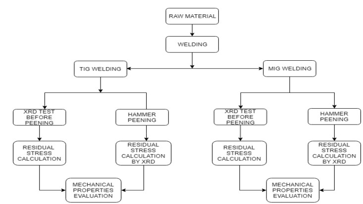
After extensive literature, the problem has been identified and the objective of the research is to conduct residual stress analysis developed on super duplex stainless steel welded joints. For this initially welded joints are prepared in both TIG and MIG welding techniques, then XRD (X-Ray Diffraction) method is conducted to predict the residual stresses developed in the welded joints, Hammer Peening method is performed on the welded joints to relieve the Residual stress and further the specimens are allowed to undergo in order to analyze the effect of Residual stresses. The entire methodology followed in this work is shown below.
4. EXPERIMENTS
Super duplex stainless steel (UNS S 32760) material has been selected as it finds plenty of applications in welded joints. The properties and composition of super duplex stainless steel are shown in the table below.
Properties
- Tensile strength 730-930 MPa
- Yield Strength 550 MPa
- Elongation 25 %
- Density 7810 kg/m3
- Hardness 290 HB
- High resistance to pitting and crevice corrosion
- High resistance to stress corrosion cracking

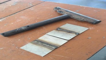
8 specimens of super duplex stainless steel material of dimensions of 45 mm x 66 mm x 3 mm are prepared and welded in both TIG and MIG methods.
4.1 TIG WELDING
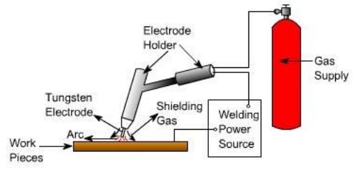
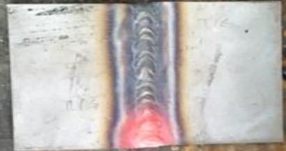
2 Specimens were prepared as butt joints using Tungsten inert gas welding. Schematic representation of TIG welding is shown in fig below and the set-up used along with the operating conditions under which welding is performed is shown in the table below.
Specifications

Operating conditions

FILLER MATERIAL
UNS S 332760 filler material is used for TIG welding, the composition and properties of filler material as follows.
PROPERTIES
Tensile strength 730-930 MPa Yield strength 550 MPa Elongation 25 % Density 7810 kg/m3 Hardness 290 HB High resistance to pitting and crevice corrosion High resistance to stress corrosion cracking
COMPOSITION


4.2 MIG WELDING
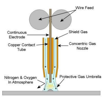
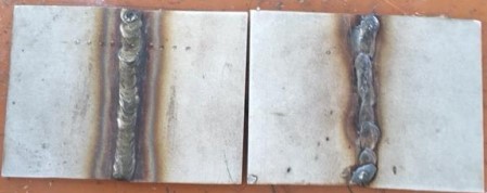
This process is based on the principle of developing weld by melting faying surfaces of the base metal using the heat produced by a welding arc established between the base metal and a consumable electrode. Welding arc and weld pool are well protected by a jet of shielding inactive gas coming out of the nozzle and forming a shroud around the arc and weld. MIG weld is not considered as clean as TIG weld. The difference in the cleanliness of the weld produced by MIG and TIG welding is primarily attributed to the variation in the effectiveness of shielding gas to protect the weld pool in case of the above two processes. Effectiveness of shielding in two processes is mainly determined by two characteristics of the welding arc namely stability of the welding arc and length of arc besides other welding-related parameters such as type of shielding gas, the flow rate of shielding gas, the distance between nozzle and work-price. The MIG arc is relatively longer and less stable than the TIG arc. The difference in the stability of two welding arcs is primarily due to the fact that in MIG arc is established between the base metal and consumable electrode (which is consumed continuously during welding) while TIG welding arc is established between the base metal and the non-consumable tungsten electrode.
Specifications

Operating conditions

4.3 XRD ( X-Ray Diffraction )
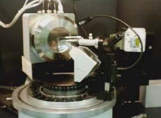
Residual stresses formed during welding can be predicted using XRD ( X-Ray Diffraction) methods. In this Research the specimens joined in both TIG and MIG welding have been undergone XRD test. The machine used for the test along with the specifications is shown below.
Diffraction methods of residual stress determination basically measure the angles at which the maximum diffracted intensity take place when a crystalline sample is subjected to x-rays. From these angles, it is possible to obtain the interplanar spacing of the diffraction planes using Bragg’s law. If the residual stresses exist within the sample, then the d spacing will be different than that of an unstressed state. This difference is proportional to the magnitude of the residual stress.
HISTORY OF XRD TECHNIQUE
In early 1895, W. C. Roentgen (1845-1923) discovered that if the electrons are accelerated by a high voltage in a vacuum tube and allowed to strike a glass or metal surface, fluorescent minerals some distance away would glow, and the film would become exposed. He attributed these effects to a new type of radiation which is different from cathode rays. They were given the name X-rays which means an unknown quantity. X- rays are produced similar to Roentgen’s today.
X-rays are produced in a standard way: by accelerating electrons with a high voltage and allowing them to collide with a metal target. Electrons are produced by heating a tungsten filament cathode in a vacuum. The cathode is as a high negative potential, and the electrons are accelerated toward the anode, which is at ground potential. Then the electrons hit the anode with a very high velocity. The loss of energy as a result of the impact is manifested as x-rays.
Absorption of X-rays
X-rays are attenuated when they pass through matter, thus the transmitted beam is weaker than the incident beam. Many different processes cause a decrease in the incident beam. Scattering (coherent & incoherent), heat production or excitations of photoelectrons, etc. are some of the contributors. The total loss in the intensity is termed absorption. The attenuation related to the thickness of an infinitesimal slab is given by the relation.
Scattering of X-rays
When a beam of x-rays is incident on the specimen, the photons collide with the electrons and scatter in different directions. There are two types of collisions. The first type is elastic and the second one is inelastic. The former is the case when the x-rays collide with the electrons that are tightly bound to the nucleus (usually the inner orbital electrons). There is no momentum transfer between the photon and electron which means scattered photon has the same energy and wavelength after the collision. This type of scattering is called coherent scattering (Figure 2.3). On the other hand, for the inelastic collision, there is a 14 momentum transfer from photon to the electron. Due to this momentum transfer, photon losses energy and has a longer wavelength. In the former, there is a relation between phases of the incident and scattered x-rays, whereas this is not the case for the latter. Latter is called Compton modified scattering or Incoherent scattering. In both cases, the photons are scattered in all directions.
4.4 Hammer Peening
Peening is the process of working a metal’s surface to improve its material properties, usually by mechanical means, such as hammer blows, by blasting with the shot (Shot Peening) or blasts of light beams with laser peening. Peening is normally a cold work process, with laser peening being a notable exception. It tends to expand the surface of the cold metal, thereby inducing compressive stresses or relieving tensile stresses already present. Peening can also encourage strain hardening of the surface metal.
4.5 HARDNESS TEST
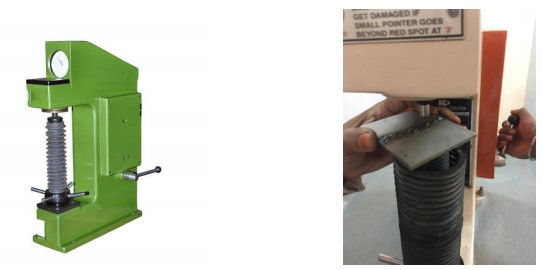
The hardness test is a mechanical test which is performed to predict the Hardness of the material so that it can be used in engineering design, analysis of structures, and materials development. The principal purpose of the hardness test is to determine the suitability of a material for a given application or the particular treatment to which the material has been subjected. The ease with which the hardness test can be made has made it the most common method of inspection for metals and alloys.
INTRODUCTION
Hardness is defined as the resistance of a material to permanent deformation such as indentation, wear, abrasion, scratch. Principally, the importance of hardness testing has to do with the relationship between hardness and other properties of the material. For example, both the hardness test and tensile test measures the resistance of a metal to plastic flow, and the results of these tests may closely parallel each other. The hardness test is preferred because it is simple, easy, and relatively nondestructive. There are many hardness tests currently in use. The necessity for all these different hardness tests is due to the need for categorizing the great range of hardness from soft rubber to hard ceramics.
Rockwell Hardness Test
The Rockwell hardness test method consists of indenting the test material with a diamond cone or hardened steel ball indenter. The indenter is forced into the test material under a preliminary minor load 15 usually 10 kgf. When equilibrium has been reached, an indicating device, which follows the movements of the indenter and so responds to changes in depth of penetration of the indenter is set to a datum position. While the preliminary minor load is still applied an additional major load is applied with a resulting increase in penetration. When equilibrium has again been reached, the additional major load is removed but the preliminary minor load is still maintained. Removal of the additional major load allows a partial recovery, so reducing the depth of penetration. The permanent increase in depth of penetration, resulting from the application and removal of the additional major load is used to calculate the Rockwell hardness number.
Test performed in the welded specimens.
Specifications

Operating Conditions

4.6 HEAT TREATMENT
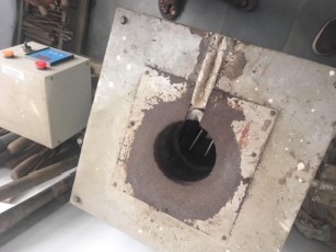
Heat treating is a group of industrial and metalworking processes used to alter the physical, and sometimes chemical, properties of a material. The most common application is metallurgical. Heat treatments are also used in the manufacture of many other materials, such as glass. Heat treatment involves the use of heating or chilling, normally to extreme temperatures, to achieve the desired result such as hardening or softening of a material. Heat treatment techniques include annealing, case hardening, precipitation strengthening, tempering, carburizing, normalizing and quenching. It is noteworthy that while the term heat treatment applies only to processes where the heating and cooling are done for the specific purpose of altering properties intentionally, heating and cooling often occur incidentally during other manufacturing processes such as hot forming or welding. The Remaining residual stresses are relieved after Heat treatment.
Operating conditions

5. RESULTS AND DISCUSSIONS
XRD (X-Ray Diffraction)
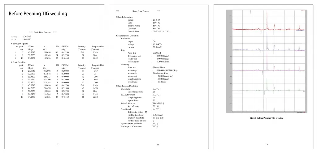
Before Peening TIG Welding
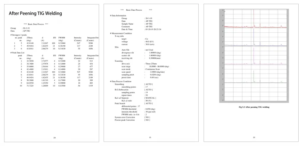
After Peening TIG Welding
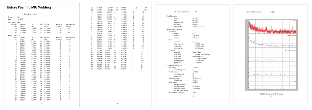
Before Peening MIG Welding
After Peening MIG Welding
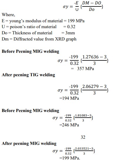
Residual stress Calculations
Hardness Test Results
Hardness test has been performed on the specimens and the Results as follows before Heat treatment as follows.
It has been observed that Hardness was more for the specimens in which residual stresses were less and so it can be concluded that residual stresses Decrease the hardness of the welded joints. The hardness of the material at various locations of the joint has plotted on the graph.
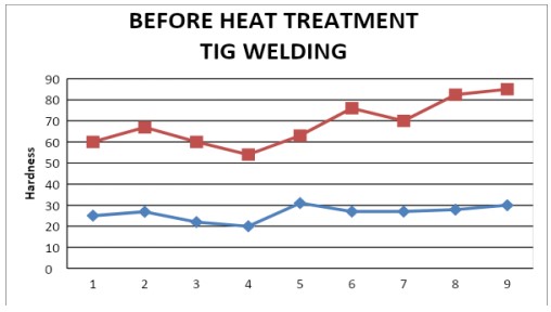
The average value of Hardness before peening = 26.32 HRC
The average value of hardness after peening = 43 HRC
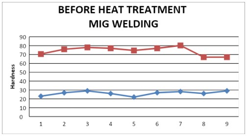
The average value of Hardness before peening = 26.34 HRC
The average value of hardness after peening = 46.77 HRC
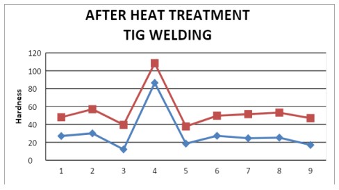
The average value of Hardness before peening = 21.04 HRC
The average value of hardness after peening = 24.86 HRC
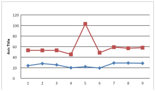
The average value of Hardness before peening = 25.04 HRC
The average value of hardness after peening = 33.86 HRC
6. CONCLUSION
In this research work, study & investigation of residual stresses developed in TIG & MIG welded joints is done. The conclusions of the research are as follows.
- By XRD method, Residual stresses developed before peening & after peening were 357 MPa and 194 MPa in TIG welding and 246 MPa and 199 MPa in MIG welding.
- Residual stresses decrease the Hardness of the welded joints ● Hammer peening after welding reduces the residual stresses developed during welding
- The hardness of the material after Peening is increased in both TIG & MIG welded joints.
- Residual stresses after peening are decreased in both TIG & MIG Welded joints
- The lifespan of the welded joints is increased
SCOPE FOR FUTURE WORK
Further mechanical properties evaluation can also be performed on both the welded joints and we can know the properties and their behaviour and resistance to the seawater applications. FEM analysis can also be done for both welded joints and comparing both results of the welded joints.
Keywords: Residual Stress analysis, Residual Stress analysis of a welded joint. Residual stress analysis using the XRD.


Leave a Reply