Metals and alloys have many useful engineering properties and so have a widespread application in engineering designs. Iron and its alloys (principally steel) account for about 90% of the world’s production of metals, mainly because of their combination of good strength, toughness, and ductility at a relatively low cost. Each metal has special properties for engineering designs and is used after a comparative cost analysis with other metals and materials. Let us see the Production of Iron and Steel.
Alloys based on iron are called ferrous alloys, and those based on the other metals are called nonferrous alloys.
Let us see the processing and production of iron and steel.
Production of Pig Iron in a Blast Furnace
Most iron is extracted from iron ores in large blast furnaces. Following is an example of the blast furnace schematic.
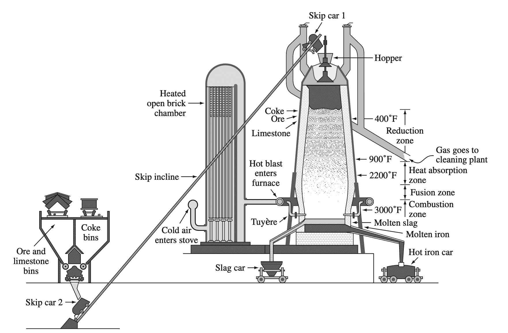
In the blast furnace, coke (carbon) acts as a reducing agent to reduce iron oxides (mainly Fe2O3) to produce raw pig iron, which contains about 4% carbon along with some other impurities according to the typical reaction
Fe2O3 + 3CO → 2Fe + 3CO2
The pig iron from the blast furnace is usually transferred in the liquid state to a steelmaking furnace.
Steelmaking and Processing of Major Steel Product Forms
Plain-carbon steels are essentially alloys of iron and carbon with up to about 1.2% carbon. However, the majority of the steel contains less than 0.5% carbon. Most steels are made by oxidizing the carbon and other impurities in the pig iron until the carbon content of the iron is reduced to the required level.
The most commonly used process for converting pig iron into steel is the basic oxygen process. In this process, pig iron and up to about 30% steel scrap is charged into a barrel-shaped refractory-lined converter into which an oxygen lance is inserted as shown in the below figure.
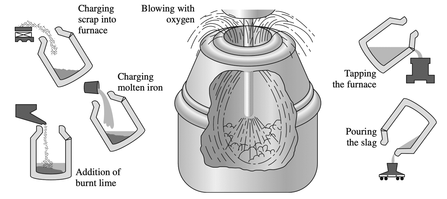
Pure oxygen from the lance reacts with the liquid bath to form iron oxide. Carbon in the steel then reacts with the iron oxide to form carbon monoxide:
FeO + C → Fe + CO
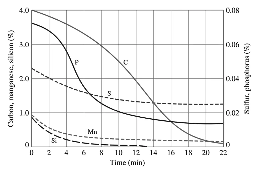
Immediately before the oxygen reaction starts, slag-forming fluxes (chiefly lime) are added in controlled amounts. In this process, the carbon content of the steel can be drastically lowered by about 22 min along with a reduction in the concentration of impurities such as sulfur and phosphorus.
The molten steel from the converter is either cast in stationary molds or continuously cast into long slabs from which long sections are periodically cut off.
Today approximately 96% of the steel is cast continuously, with about 4000 ingots still being cast individually. However, about one-half of the raw steel is produced by recycling old steel, such as junk cars and old appliances.
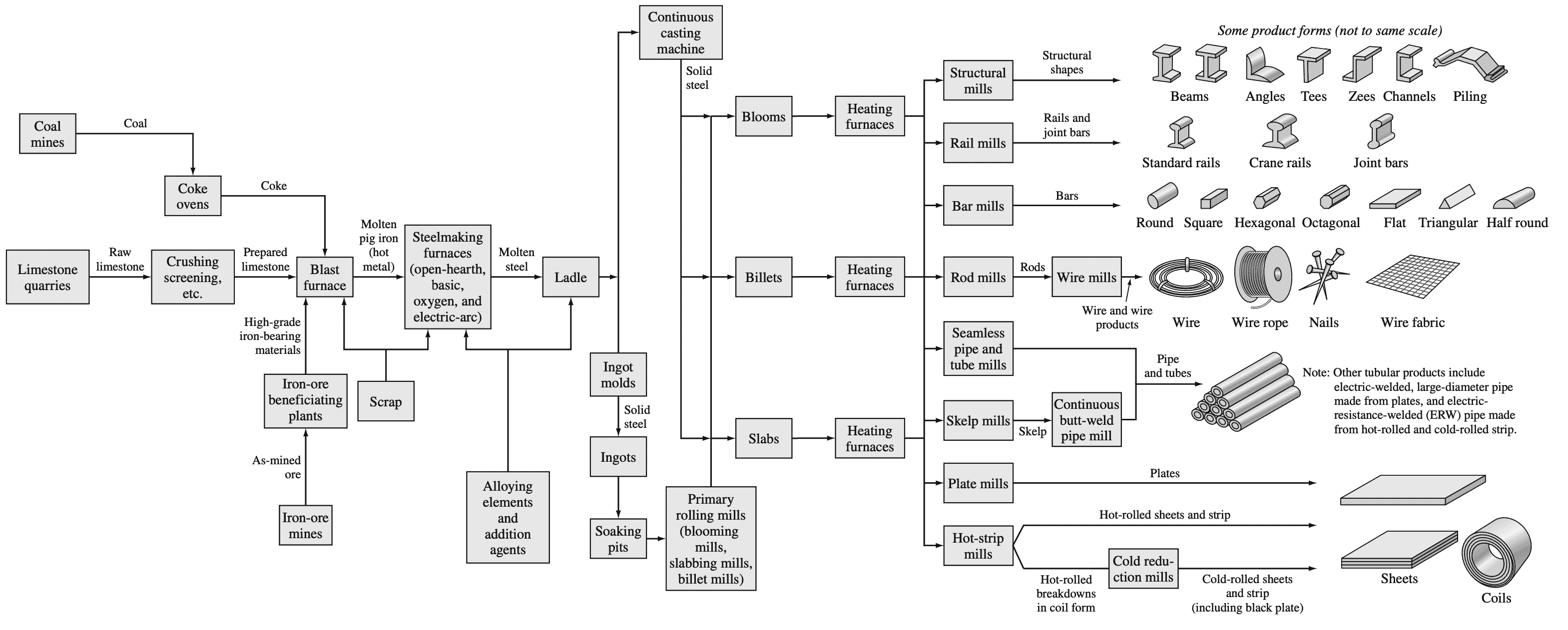
After being cast, the ingots are heated in a soaking pit and hot-rolled into slabs, billets, or blooms. The slabs are subsequently hot- and cold-rolled into steel sheet and plate. The billets are hot- and cold-rolled into bars, rods, and wire, while blooms are hot- and cold-rolled into shapes such as I beams
and rails.
Following is a flow diagram that summarizes the principal process steps involved in converting raw materials into major steel product forms.
The Iron-Carbon System
Iron–carbon alloys containing from a very small amount (about 0.03%) to about 1.2% carbon, 0.25 to 1.00% manganese, and minor amounts of other elements are termed plain-carbon steels. However, for purposes of this section of the book, plain-carbon steels will be treated as essentially iron-carbon binary alloys. The effects of other elements in steel will be dealt with in later sections.
Iron-Iron-Carbide (Fe–Fe3C) Phase Diagram
The phases present in very slowly cooled iron-carbon alloys at various temperatures and compositions of iron with up to 6.67% carbon are shown in the Fe–Fe3C phase diagram shown below.
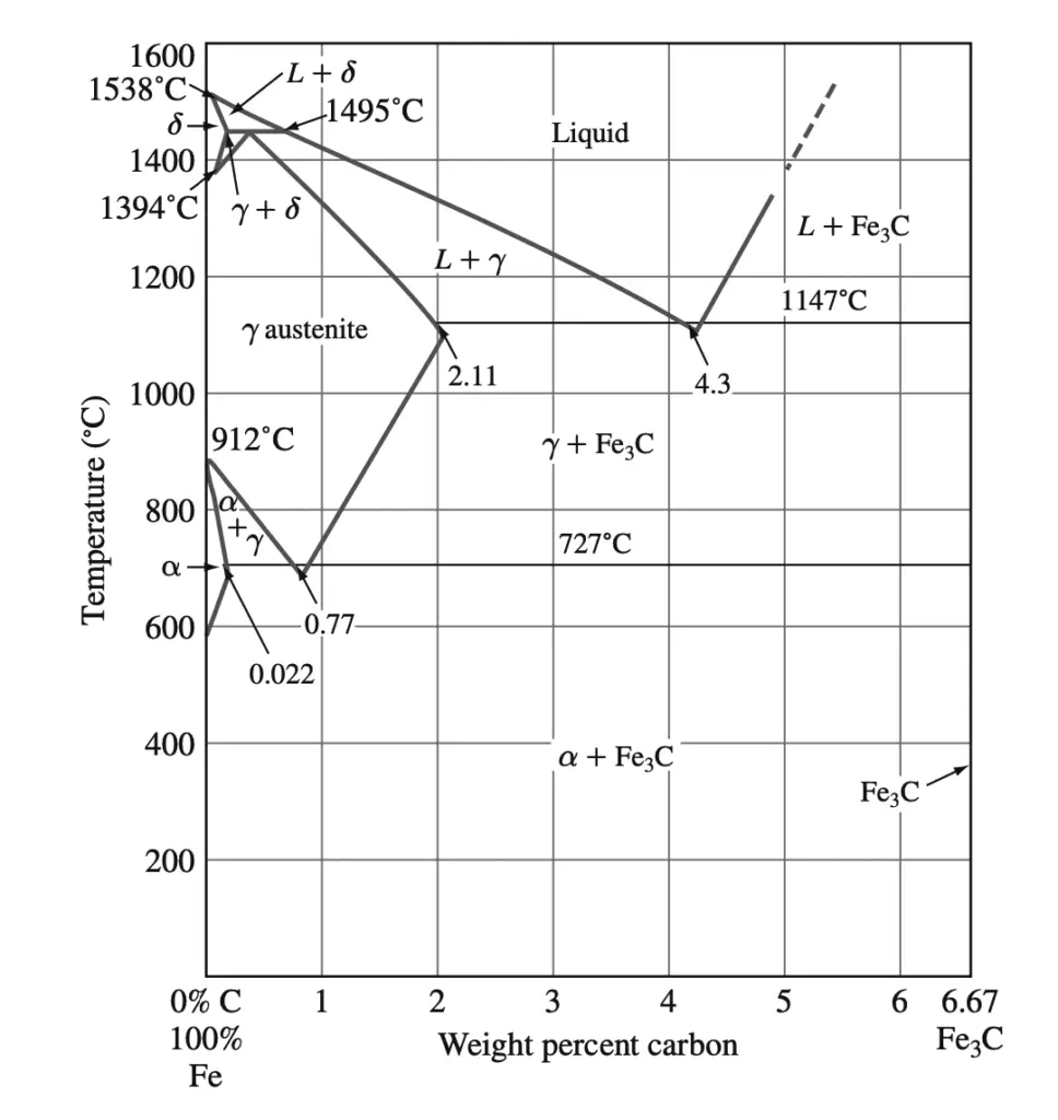
This phase diagram is not a true equilibrium diagram since the compound iron carbide (Fe3C) that is formed is not a true equilibrium phase. Under certain conditions, Fe3C, which is called cementite, can decompose into the more stable phases of iron and carbon (graphite). However, for most practical conditions, Fe3C is very stable and will therefore be treated as an equilibrium phase.
Solid Phases in the Fe–Fe3C Phase Diagram
The above Fe–Fe3C phase diagram contains the following solid phases:
- α ferrite,
- austenite (γ),
- cementite (Fe3C)
- δ ferrite
1. α ferrite: This phase is an interstitial solid solution of carbon in the BCC iron crystal lattice. As indicated by the Fe–Fe3C phase diagram, carbon is only slightly soluble in α ferrite, reaching a maximum solid solubility of 0.022% at 727°C. The solubility of carbon in α ferrite decreases to 0.005% at 0°C.
2. Austenite (γ): The interstitial solid solution of carbon in γ iron is called austenite. Austenite has an FCC crystal structure and a much higher solid solubility for carbon than α ferrite. The solid solubility of carbon in austenite is a maximum of 2.11% at 1148°C and decreases to 0.77% at 727°C.
3. Cementite (Fe3C): The intermetallic compound Fe3C is called cementite. Cementite has negligible solubility limits and composition of 6.67% C and 93.3% Fe. Cementite is a hard and brittle compound.
4. δ ferrite: The interstitial solid solution of carbon in δ iron is called δ ferrite. It has a BCC crystal structure like α ferrite but with a greater lattice constant. The maximum solid solubility of carbon in δ ferrite is 0.09% at 1465°C.
Invariant Reactions in the Fe–Fe3C Phase Diagram
Peritectic Reaction
At the peritectic reaction point, a liquid of 0.53% C combines with δ ferrite of 0.09% C to form γ austenite of 0.17% C. This reaction, which occurs at 1495°C, can be written as
Liquid (0.53% C) + δ(0.09% C) → γ (0.17% C) ….. @1495°C
δ Ferrite is a high-temperature phase and so is not encountered in plain-carbon steels at lower temperatures.
Eutectic Reaction
At the eutectic reaction point, liquid of 4.3% forms γ austenite of 2.11% C and the intermetallic compound Fe3C (cementite), which contains 6.67% C.
This reaction, which occurs at 1148°C, can be written as
Liquid (4.3% C) → γ austenite (2.11% C) + Fe3C (6.67% C) …… @1148°C
This reaction is not encountered in plain-carbon steels because their carbon contents are too low.
Eutectoid Reaction
At the eutectoid reaction point, solid austenite of 0.77% C produces α ferrite with 0.022% C and Fe3C (cementite) that contains 6.67% C. This reaction, which occurs at 727°C, can be written as
γ austenite (0.77% C)→ α ferrite (0.022% C) + Fe3C (6.67% C) ….. @727°C
This eutectoid reaction, which takes place completely in the solid-state, is important for some of the heat treatments of plain-carbon steels.
Plain-carbon steel that contains 0.77% C is called eutectoid steel since a eutectoid structure of α ferrite and Fe3C is formed when austenite of this composition is slowly cooled below the eutectoid temperature. If plain-carbon steel contains less than 0.77% C, it is termed hypereutectoid steel, and if the steel contains more than 0.77% C, it is designated hyper eutectoid steel.

Can you please provide me the name of the textbook you used for this post. I had the book and lost it.