In the Design of any machine elements, it is necessary to follow the Geometric dimensioning and tolerancing for the Holes or shafts. The maximum material condition is the feature of the size where it can be called out for a hole or a shaft feature on the drawing.
Maximum Material Condition (MMC)
It refers to a feature of size. (The feature of size is nothing but the set of parallel surfaces associated with the size dimension.)
This is a condition where there exists a maximum amount of material within the given dimension tolerance zone for the part or the feature.
If the MMC callout is on the hole feature then the hole feature should have the smallest size. if the MMC callout is on the shaft or pin feature then the shaft or pin feature should have the largest size within the tolerance zone.
The reason to call out the MMC, to limit the amount of interference between the parts. a shaft that must go through a hole with clearance between the two.
The main application of this MMC is for clearance applications. MMC clears the biggest size of bolt.
See the below MMC conditions for Pin and Hole.
MMC condition for a pin
The pin will have the maximum diameter within the tolerance limit. (i.e Ø10.5)
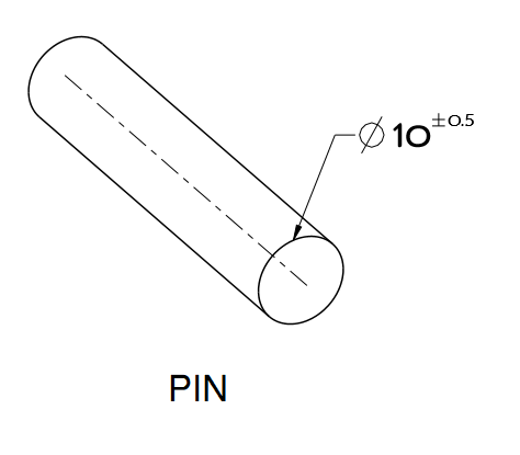
Gauging maximum material condition for a pin
A pin always fit into a hole, when the pin is in the MMC condition. So that we will design the Hole Gauge for the pin. so this hole gauge controls the maximum material condition for the pin. this gauge is called GO GAUGE.
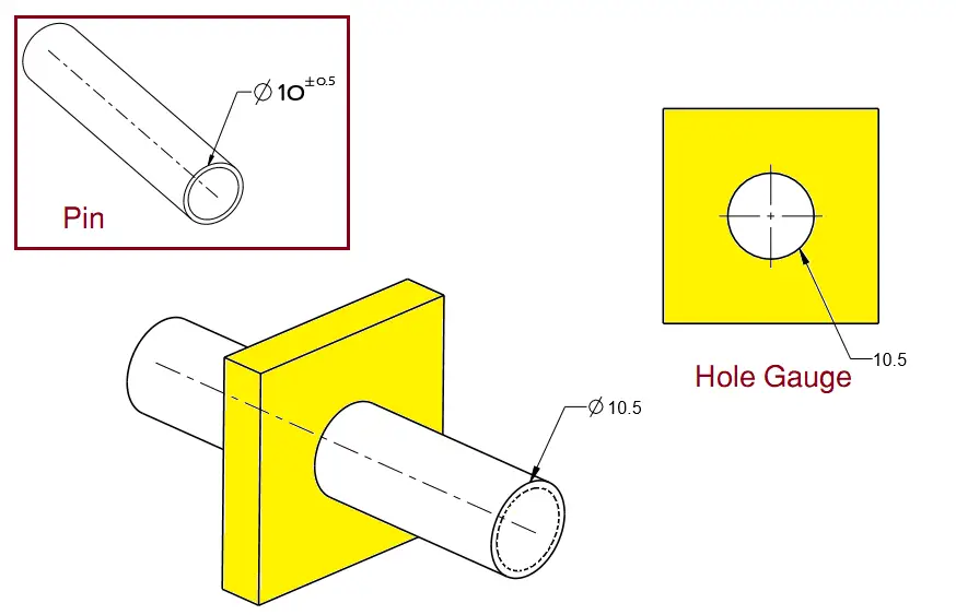
The Hole gauge is having the diameter same as the Pin maximum diameter(Ø).
The formula to find the Hole Gauge Diameter(Ø)= Max Diameter(Ø) of MMC Pin+GD&T Symbol tolerance(if mentioned. In the above picture there is no GD&T )
The Hole gauge may be made slightly larger (a few microns) than the MMC to account for straightness or tolerance issues.
MMC condition for Hole
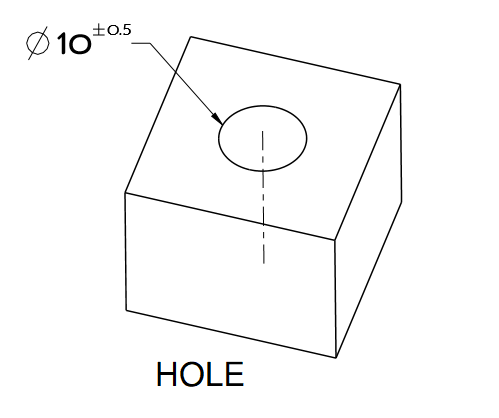
The Hole will have a small diameter within the tolerance limit. (i.e Ø9.5)
Gauging maximum material condition for Hole
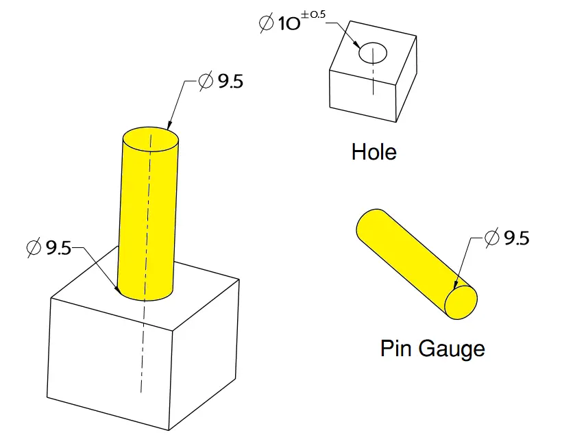
a pin always fits into a hole when the hole is at MMC So that we will design the Pin Gauge for the pin. so this pin gauge controls the maximum material condition for the hole.
The Pin gauge is having the diameter same as the Hole Minimum diameter(Ø).
The formula to find the Pin Gauge Diameter(Ø)= Min Diameter(Ø) of MMC Hole-GD&T Symbol tolerance(if mentioned. In the above picture there is no GD&T )
The pin gauge may be made slightly smaller (a few microns) than the MMC to account for straightness or tolerance issues.
Conclusion: MMC is used when we deal with the clearance fits. MMC Hole will have a minimum diameter and, MMC Pin will have a Maximum diameter within the tolerance limits.
Where can we apply Maximum Material Condition?
- True Position(common for MMC)
- Straightness
- Parallelism
- Perpendicularity
- Angularity
The feature of Size Callouts in GD&Ts
- Maximum material Condition
- Least Material Condition
- Regardless of the feature of size
Regardless of the feature of size
When there is no call out to Maximum Material Condition or Least Material Condition, the part, by default, is measured regardless of feature size (RFS).

It is vital to follow the Geometric dimensioning and tolerancing for the Holes or shafts in the design of any machine element. Thank you so much for this blog!