In machine Design, each machine member will be mated with another machine member with the defined fit. There are the different type of fits available. They are Clearance Interference, Transition fits. These fits are controlled with some Tolerances and allowances according to some Standards. Actually, these tolerances values can be calculated. According to Indian Standard system of limits and Fits, we have tolerance grades and relative magnitudes, Fundamental deviations. With the help of these, we can calculate the tolerances for the hole or shaft.

To begin with the calculation of hole or shaft tolerances we must understand what is a fundamental deviation.
The fundamental deviation is an allowance rather than tolerance. The allowance is simply the deviation between the hole minimum diameter to the shaft maximum diameter.
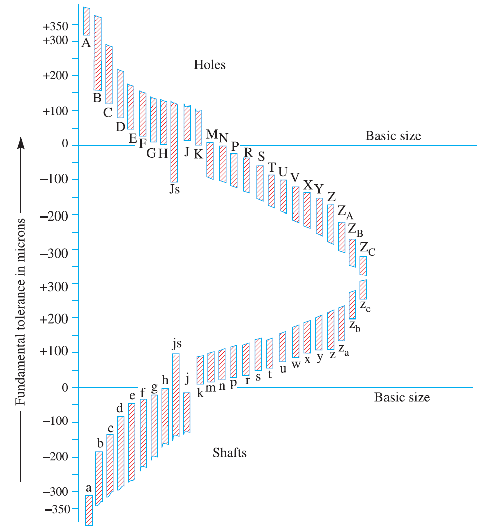
See the below the Fundamental deviation chart

There is a total of 25 fundamental deviations available. All these 25 deviations are represented with the alphabets for holes and shafts. These alphabets are case-sensitive. Block letters are used to represent the hole and small letters are used to represent the shaft deviations. all these deviations are in micrometres(Microns)
Holes deviations: A, B, C, D, E, F, G, H, JS, J, K, M, N, P, R, S, T, U, W, X, Y, Z, ZA, ZB, ZC
Shafts deviations: a, b, c, d, e, f, g, h, js, j, k, m, n, p, r, s, t, u, w, x, y, z, za, zb, zc
Next, we need to know the International tolerance Grades
International Tolerance Grades
According to Indian standard system of limits and fits, there are total 18 International Tolerance(IT) grades. These grades determine the tolerances for the given designated shaft value. The following are the International tolerance grades.
IT01, IT0, IT1, IT2, IT3, IT4, IT5, IT6, IT7, IT8, IT9, IT10, IT11, IT12, IT13, IT14, IT15, IT16.
But how we will use this tolerance grades?
Here is how we use these grades.
IT01 to IT4 – For the production of gauges, plug gauges, measuring instruments
IT5 to IT 7 – For fits in precision engineering applications
IT8 to IT11 – For General Engineering
IT12 to IT14 – For Sheet metal working or press working
IT15 to IT16 – For processes like casting, general cutting work
| Tolerance Grade | IT5 | IT6 | IT7 | IT8 | IT9 | IT10 | IT11 | IT12 | IT13 | IT14 | IT15 | IT16 |
| Magnitude | 7i | 10i | 16i | 25i | 40i | 64i | 100i | 160i | 250i | 400i | 640i | 1000i |
Where
![]() (Units in Microns, 1Micron = 0.001)
(Units in Microns, 1Micron = 0.001)
D = Geometric mean diameter in mm
(Tolerances for the grades IT2, IT3, IT4 are scaled approximately)
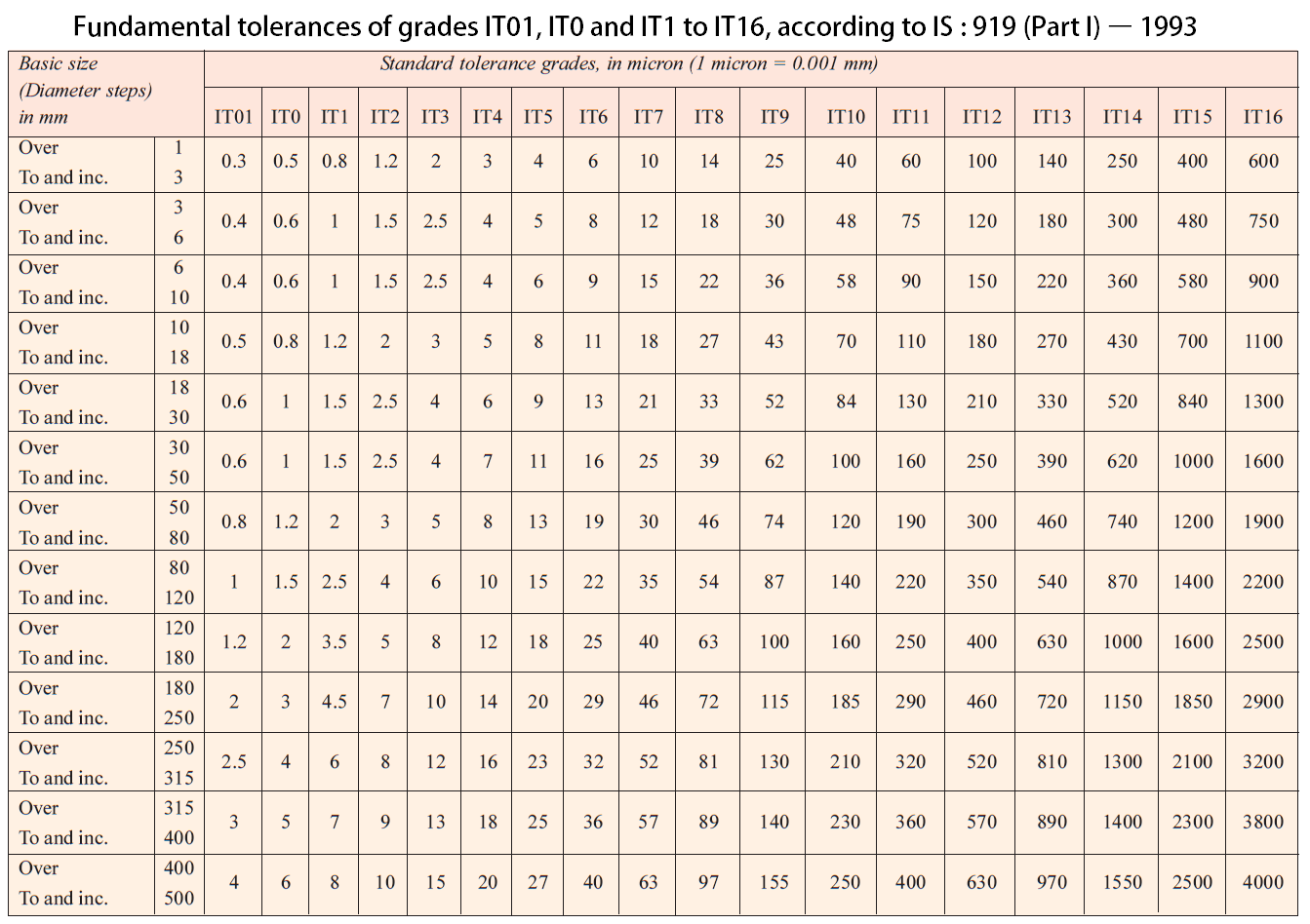
These tolerance values are calculated and listed in the following table For all 18 grades according to the diameter steps range from 1 to 500mm

Now we have an idea what is a fundamental deviation and a tolerance right? Let’s go to next
For example, If a shaft designated as 40H8/f7 it represents that 40mm id=s the basic size and the tolerance grade for the hole is 8(IT8) with a deviation H and the tolerance for the shaft is 7 (IT7) with the shaft deviation of f
Let’s see how we can calculate Tolerances and the Fundamental deviations for the Hole or a Shaft.
Procedure to Calculate tolerance values for shaft or a hole
1. Calculating Fundamental Deviation
a) Calculation of Fundamental Deviation for Shafts
The upper deviation and the lower deviation for the shafts are represented as es, ei
IT may be noted that the shafts from a to h, the upper deviation are considered, whereas the shafts j to zc, The lower deviation will be considered.
ei = es – IT (or) es = ei +IT

Exception: For js the shaft (Upper and lower) deviation is ±IT/2
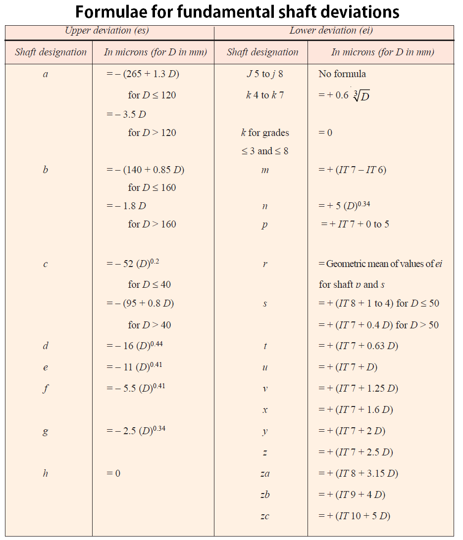
with these formulas, the deviation can be calculated
where
D = Geometric mean diameter in mm
it will be taken from the below table
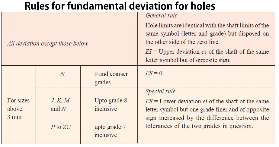
b) Calculation of Fundamental Deviation for Holes
The upper deviation and the lower deviation for the Hole are represented with EI, ES
EI = ES – IT (or) ES = EI + IT
See the below tabular for calculating the Deviation for the holes

Example Problem to Calculate tolerance values for shaft or a hole
Problem: Calculate the tolerances, Fundamental Deviations and limits of sizes for the shaft designated as 40H8/f7.
Solution:
A Shaft designation is given as 40H8/f7
40 is lies between the diameters 30and 50 (These values are taken from the standard Tables [Table: 1])
D = √(30×50) = 38.73
From above equation i = 0.00156 (1 micron = 0.001mm)
The relevant magnitude for the grade IT8 = 25i = 25 x 0.00156 = 0.039 …………………….i
The relevant magnitude for the grade IT7 = 16i = 16 x 0.00156 = 0.025 ……………………ii
[These values can be directly taken from the Table 1 ]
Fundamental Deviation
The fundamental Lower deviation for the hole always will be (EI) = 0 ……………. iii
Fro the Table: 2
The fundamental deviation (Upper deviation) for the shaft f
es = -5.5 (D)0.41
es = -5.5 (38.73)0.41
es = -24.63 microns (25 microns) = -0.025mm ……………….iv
The fundamental deviation (lower deviation) for the shaft f
ei = es – IT
ei = -0.025-0.025 = -0.050 ………………………v ( where IT7 = 0.025 from above)
This negative sign indicates the fundamental deviation lies below the zero line
Limits of Sizes
From above the lower deviation for the hole is (EI) = 0
The lower limit will be 40.000
The upper limit for the hole = Lower limit for hole + Tolerance value for the hole
The upper limit for the hole = 40.000+0.039 = 40.039
The hole Limits will be 40.000/40.039
The upper limit for the shaft = Lower limit for the hole(Basic Size) – Fundamental Deviation
The upper limit for the shaft = 40.000-0.025 = 39.975
The lower Limit for the shaft = Upper limit for the shaft – Tolerance For shaft
The lower Limit for the shaft = 39.975-0.025 = 39.950
The shaft limits will be 39.975/39.950
Conclusion
This is a quick calculation procedure to calculate the tolerance for the designated shaft or holes. [Reference Machine Design by RS kurmi]

Hello! Thank you for the explanation!
One thing I want to point out is that I think there is a typo in the first line of the topic 1.(a) “Calculation of Fundamental Deviation of Shafts”. Instead of “The upper deviation and the lower deviation for the shafts are represented as ei, es”, there should be written – “The upper deviation and the lower deviation for the shafts are represented as es, ei (respectively)”. As written correctly in the table 2, the upper deviation of the shaft is es and the lower one is ei.
That’s a good observation Saksham Kumar.
Really helpful. I have corrected it.
Thanks.
how do we exactly H8/f8 for shaft or hole?
can you plz explain in brief