The coefficient of Viscosity is the resistance to the flow of viscous fluid. It is denoted with the μ. Determining the Coefficient of Viscosity can be done with different experimental methods. In this article, we will derive the expression to determine the Coefficient of Viscosity also we will discuss the different experimental methods of Determining the Coefficient of Viscosity of a Fluid.

Coefficient of Viscosity Derivation
In order to derive the Coefficient of Viscosity, we need to consider a piston and Dash-pot arrangement as shown in the following figure.
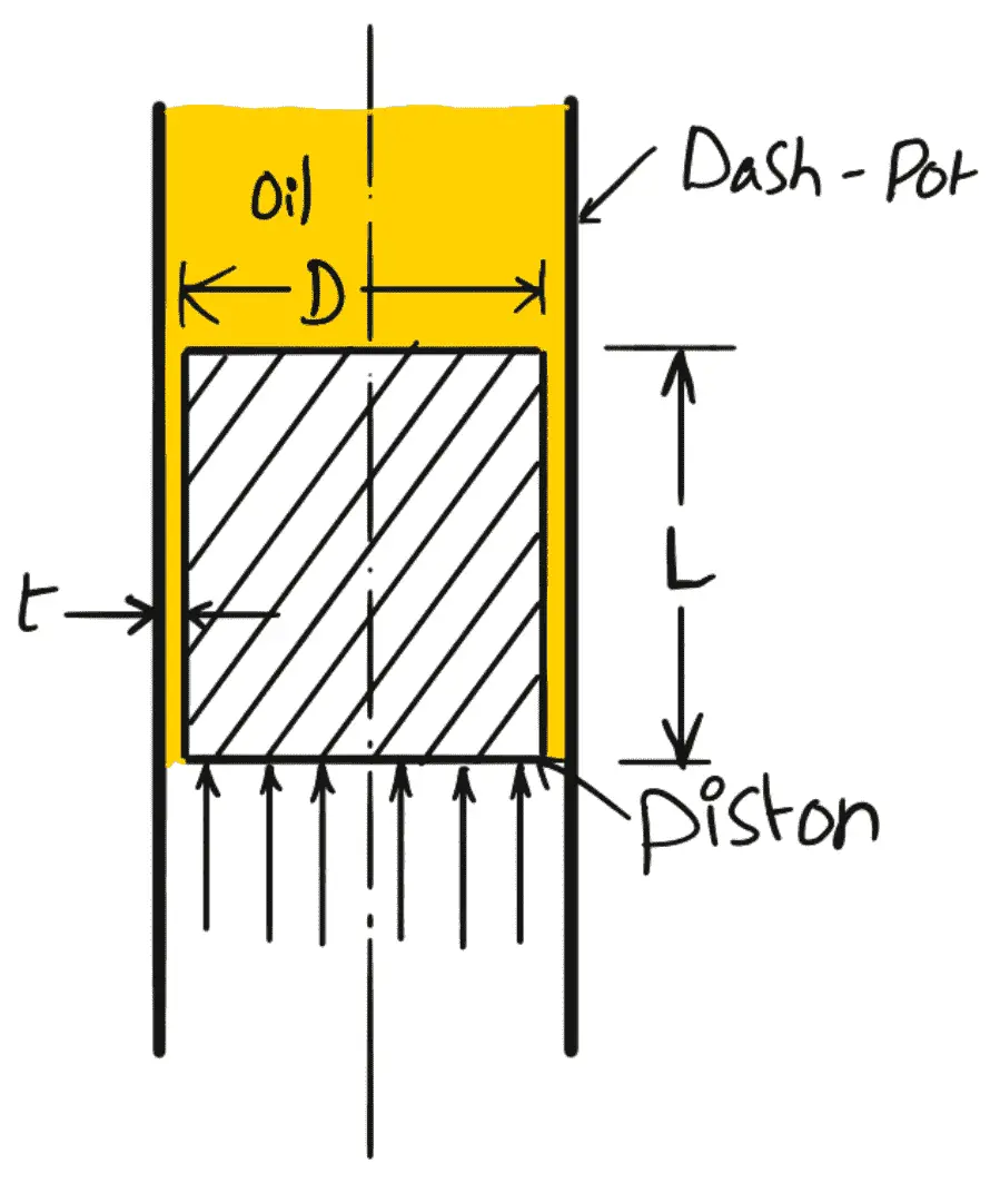
Let us consider a piston moving in a vertical dash-pot containing oil, then
Where
D = Diameter of the piston,
L = Length of the piston,
W = Weight of the piston,
μ = Viscosity of oil,
V = Velocity of the piston,
ū = Average velocity of oil in the clearance,
l = Clearance between the dash-pot and piston,
∆p = Difference of pressure intensities between the two ends of the piston.
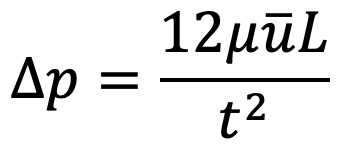
The flow of oil through clearance is similar to the viscous flow between two parallel plates. The difference of pressure for parallel plates for length ‘L’ is given by
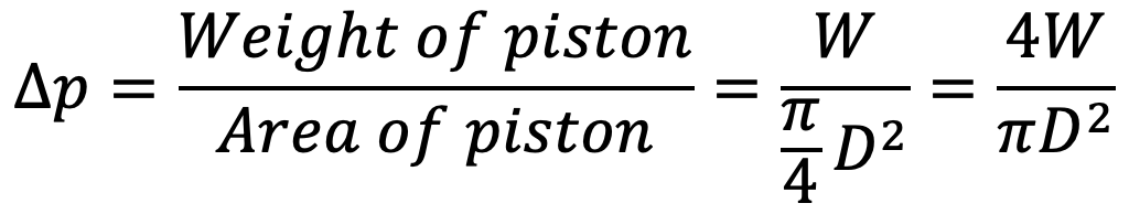
Also, the difference in pressure at the two ends of the piston can be written as
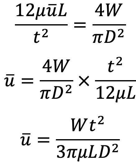
From the above two equations, we get
V is the velocity of the piston or the velocity of oil in the dash-pot in contact with the piston.
The rate of flow of oil in dash-pot = velocity × area of dash-pot
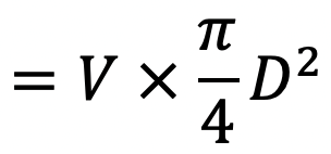
The Rate of flow through clearance = velocity through clearance × area of clearance
= ū × πD × t
Due to the continuity equation, the rate of flow through clearance must be equal to the rate of flow through the dash-pot.
We can equate the above two equations of the rate of flow for the dash-pot and the clearance, we get
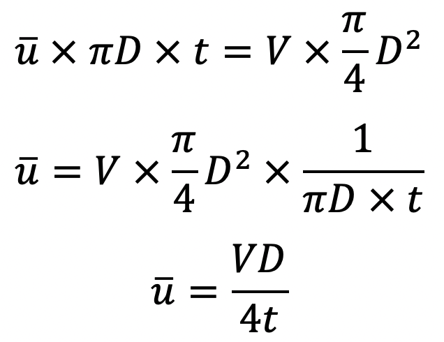
Equating the value of ū from (a) and (b), we get
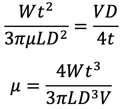
This is the equation for the Coefficient of Viscosity.
By using this equation for the Coefficient of viscosity, let us solve an example problem to calculate the coefficient of Viscosity for oil between the dash-pot and the piston.
Calculating Coefficient of Viscosity in Damper
Problem Statement: An oil dash-pot consists of a piston moving in a cylinder having oil. This arrangement is used to damp out the vibrations. The piston falls with uniform speed and covers 5 cm in 100 seconds. If an additional weight of 1.36 N is placed on the top of the piston, it falls through 5 cm in 86 seconds with uniform speed. The diameter of the piston is 7.5 cm and its length is 10 cm. The clearance between the piston and the cylinder is 0.12 cm which is uniform throughout. Find the viscosity of the oil.
Answer:
Distance covered by piston due to self-weight, = 5 cm
Time taken, = 100 sec
Additional weight = 1.36 N
Time is taken to cover 5 cm due to additional weight, = 86 sec
Diameter of the piston D = 7.5 cm = 0.075 m
Length of the piston L= 10cm = 0.1 m
Clearance l = 0.12 cm = 0.0012 m
Let the viscosity of oil = μ
Weight of piston = W
The velocity of the piston without additional weight = V
The velocity of the piston with additional weight = *V
From Equation (c), we have
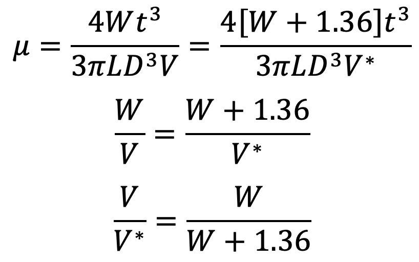
But Velocity of the piston due to self-weight of piston = V = Distance covered / Time Taken = 5/100 cm/sec
Similarly, the Velocity of the piston with additional weight = V*
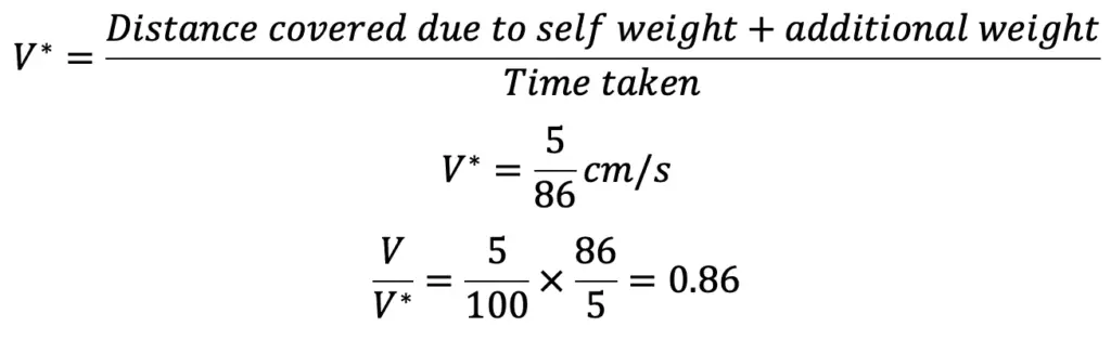
Equating the above two equations, we get
W ÷ (W + 1.36) = 0.86
W = (W + 1.36) × 0.86
W = W × 0.86 + 1.36 × 0.86
0.14 W = 1.36 × 0.86
W = 8.354 N
The weight of the piston W is 8.354 N.
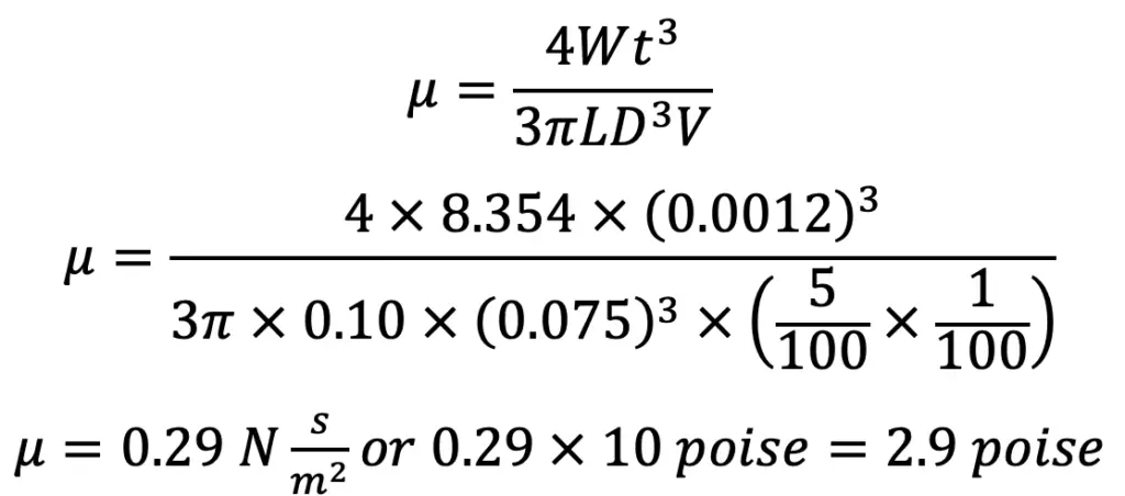
Using the coefficient of viscosity equation, we get,
Instead of calculating the Coefficient of Viscosity, there are experimental methods were developed to determine the Coefficient of Viscosity.
Methods of Determination of Coefficient of Viscosity
The following are the experimental methods for determining the coefficient of viscosity of a liquid
- Capillary tube method
- The falling sphere resistance method
- By rotating cylinder method
- Orifice type viscometer
The apparatus used for determining the viscosity of a liquid is called a viscometer.
1. Capillary Tube Method
In the capillary tube method, the viscosity of a liquid is calculated by measuring the pressure difference for a given length of the capillary tube. The Hagen Poiseuille law is used for calculating viscosity.
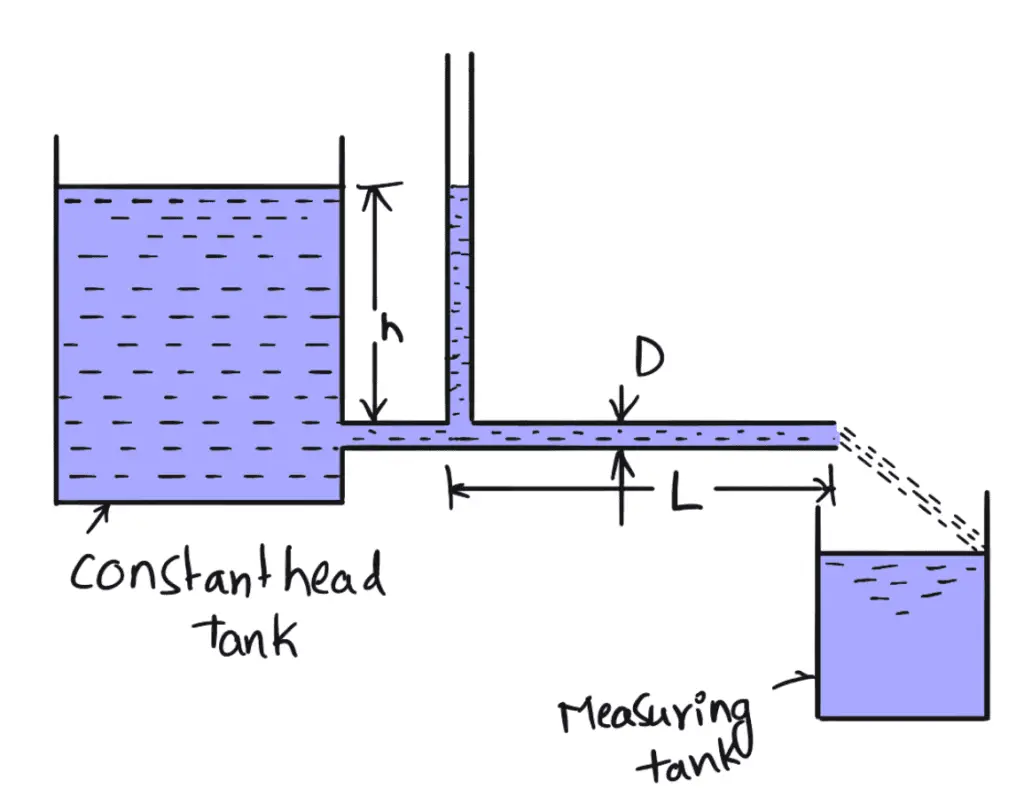
The above figure shows the capillary tube viscometer. The liquid whose viscosity is to be determined is filled in a constant head tank. The liquid is maintained at a constant temperature and is allowed to pass through the capillary tube from the constant head tank. Then, the liquid is collected in a measuring tank for a given time. Then the rate of liquid collected in the tank per second is determined. The pressure head ‘h’ is measured at a point far away from the tank as shown in the above figure
Then
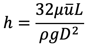
h = Difference of pressure head for length L
The pressure at the outlet is atmospheric.
Let
D = Diameter of the capillary tube
L = Length of the tube for which difference of pressure head is known
ρ = Density of fluid
μ = Coefficient of viscosity.
Using Hagen Poiseuille’s Formula
But, we know
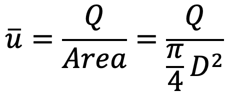
where Q is the rate of liquid flowing through the tube

Measurement of D should be done very accurately.
2. Falling Sphere Resistance Method
Falling Sphere Resistance Method method is based on Stoke’s law, according to which the drag force, F on a small sphere moving with a constant velocity, U through a viscous fluid of viscosity, μ for viscous conditions is given by
F = 3πμUD
where
d = diameter of the sphere
U = velocity of the sphere
When the sphere attains a constant velocity U, the drag force is the difference between the weight of the sphere and the buoyant force acting on it.
Let
L = distance travelled by sphere in a viscous fluid
t = time taken by sphere to cover distance l
ρs = density of the sphere
ρr = density of the fluid
W = weight of the sphere
FB = buoyant force acting on the sphere
The constant velocity of sphere U = L/t
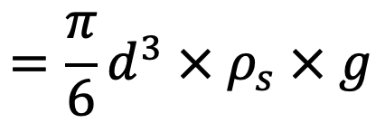
Weight of sphere W = volume × density of sphere × g
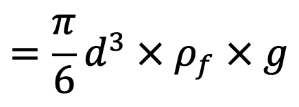
Buoyant force FB = weight of the fluid displaced
FB = volume of liquid displaced × density of fluid × g
For equilibrium
Drag force = Weight of sphere – buoyant force
F = W – FB
Substituting the values of F, W and FB, we get the following relation
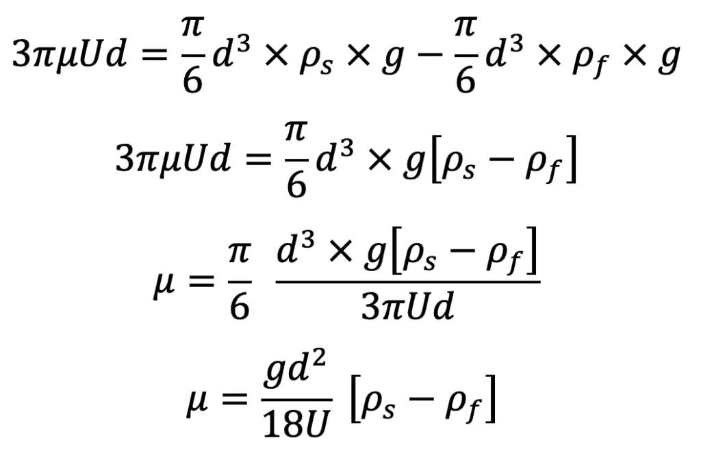
Where ρf = Density of the liquid
Hence in equation (e), the values of d, U, ρs, and ρf, are known and hence the viscosity of the liquid can be determined.
Procedure
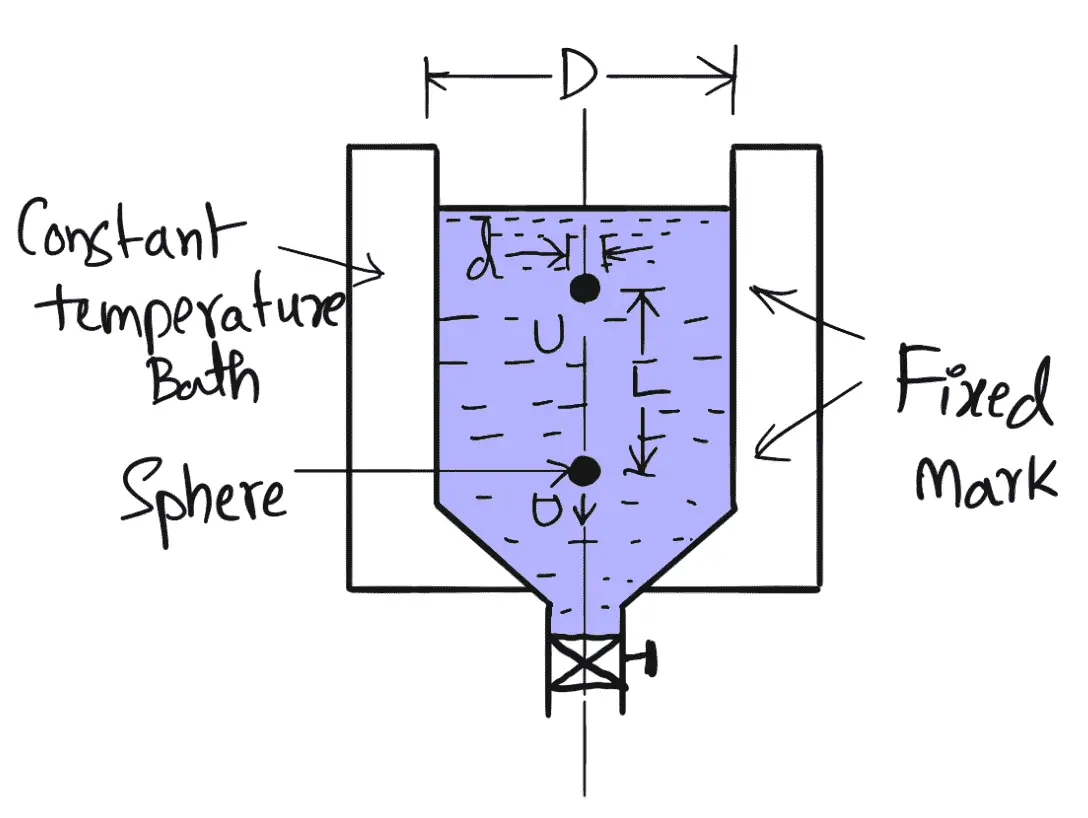
- Falling Sphere Resistance Method consists of a tall vertical transparent cylindrical tank, which is filled with the liquid whose viscosity is to be determined.
- This tank is surrounded by another transparent tank to keep the temperature of the liquid in the cylindrical tank to be constant.
- A spherical ball of small diameter ‘d’ is placed on the surface of the liquid.
- Provision is made to release this ball.
- After a short distance of travel, the ball attains a constant velocity.
- The time to travel a known vertical distance between two fixed marks on the cylindrical tank is noted to calculate the constant velocity U of the ball.
- Then with the known values of d, U, ρs, and ρf the viscosity μ of the fluid is calculated by using equation (e).
3. Rotating Cylinder Method
This Rotating Cylinder Method method consists of two concentric cylinders of radii R, and R, as shown in the following figure. The narrow space between the two cylinders is filled with the liquid whose viscosity is to be determined.
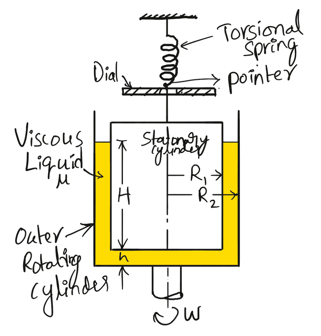
The inner cylinder is held stationary by means of a torsional spring while the outer cylinder is rotated at constant angular speed w. The torque T acting on the inner cylinder is measured by the torsional spring. The torque on the inner cylinder must be equal and opposite to the torque applied on the outer cylinder. The torque applied on the outer cylinder is due to viscous resistance provided by the liquid in the annular space and at the bottom of the inner cylinder.
Let
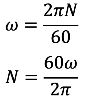
ω = angular speed of the outer cylinder
Tangential (peripheral) speed of the outer cylinder = ω x R2
The tangential velocity of the liquid layer in contact with the outer cylinder will be equal to the tangential velocity of the outer cylinder.
The velocity of the liquid layer with the outer cylinder = ω x R2
The velocity of the liquid layer with the inner cylinder = 0
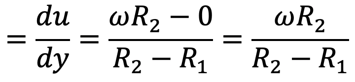
Velocity gradient over the radial distance (R2 – R1)
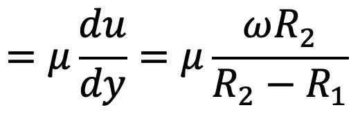
The Shear stress (τ) we can write
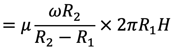
Shear force (F) = shear stress × area of surface
F = τ × 2π R1 H
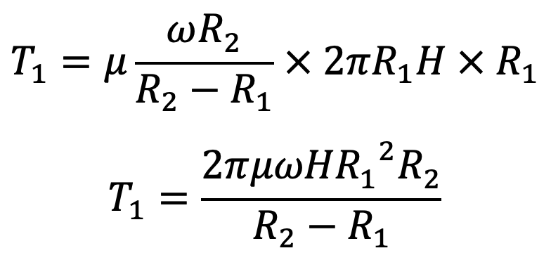
The torque T1, on the inner cylinder due to the shearing action of the liquid in the annular space is
T1 = shear force × radius
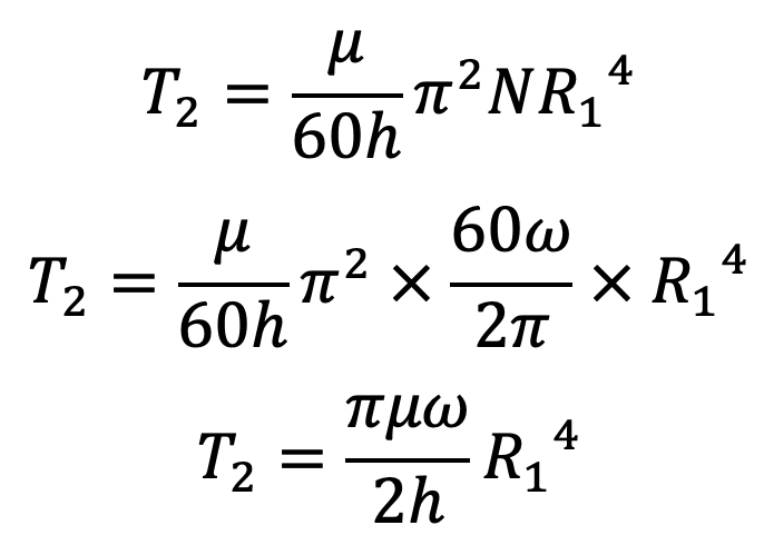
If the gap between the bottom of the two cylinders is ‘h’, then the torque applied to the inner cylinder (T2) is given by the equation we know
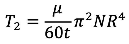
But here, we know R = R1 and t = h and
Substituting these values in the above T2 equation we get,
Total torque T acting on the inner cylinder can be written as
T = T1 + T2
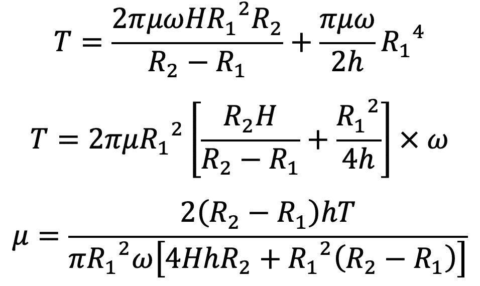
where
T = torque measured by the strain of the torsional spring
R1 R2 = radii of the inner and outer cylinder
h = clearance at the bottom of cylinders
H = height of liquid in annular space
μ = co-efficient of viscosity to be determined
Hence, the value of μ can be calculated from equation (f).
4. Orifice Type Viscometer
In the Orifice Type Viscometer method, the time taken by a certain quantity of the liquid whose viscosity is to be determined, to flow through a short capillary tube is noted down. The coefficient of viscosity is then obtained by comparing it with the coefficient of viscosity of a liquid whose viscosity is known or by the use of conversion factors.
Viscometers such as Saybolt, Redwood or Engler are usually used. The principle for all three viscometers is the same. In the United Kingdom, Redwood viscometer is used while in the U.S.A., Saybolt viscometer is commonly used.
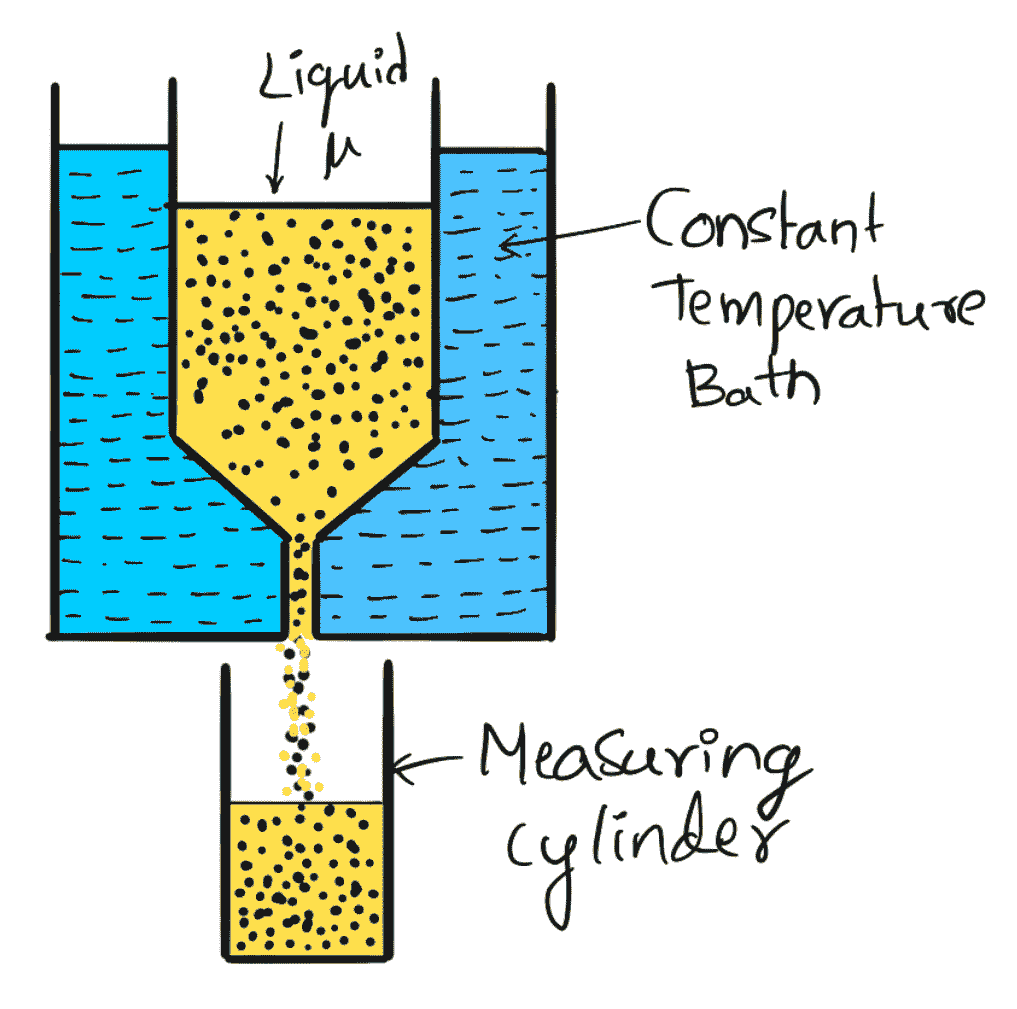
The above figure shows the Saybolt viscometer, which consists of a tank at the bottom of which a short capillary tube is fitted. In this tank, the liquid whose viscosity is to be determined is filled. This tank is surrounded by another tank, called a constant temperature bath. The liquid is allowed to flow through a capillary tube at a standard temperature. The time taken by 60 c.c. for the liquid to flow through the capillary tube is noted down. The initial height of liquid in the tank is previously adjusted to a standard height.
From the time measurement, the kinematic viscosity of the liquid is known from the relation
v = At – B/t
where
A = 0.24
B = 190
t = time noted in seconds
v= kinematic viscosity in stokes
This is all about how we can calculate the Coefficient of Viscosity of a Fluid and different experimental methods to determine the Coefficient of Viscosity. Let us know what you think about this article in the comment section below.
Leave a Reply