When a large amount of power is to be transmitted over long distances from one pulley to another (i.e. when the pulleys are up to 150 meters apart), then wire ropes are used. The wire ropes are widely used in elevators, mine hoists, cranes, conveyors, hauling devices, and suspension bridges. The wire ropes run on grooved pulleys but they rest on the bottom of the grooves and are not wedged between the sides of the grooves. Let us discuss how we can Calculate Stresses in Wire Ropes.

The wire ropes are made from cold-drawn wires in order to increase strength and durability. It may be noted that the strength of the wire rope increases as its size decreases. The various materials used for wire ropes in order of increasing strength are wrought iron, cast steel, extra strong cast steel, plow steel, and alloy steel. For certain purposes, the wire ropes may also be made of copper, bronze, aluminum alloys, and stainless steel.
Stresses in Wire Ropes
A wire rope is subjected to the following types of stresses:
- Direct stress due to axial load lifted and weight of the rope
- Bending stress when the rope winds around the sheave or drum.
- Stresses during starting and stopping
- Stress due to change in speed
- Effective stress
Let us discuss these in a detailed manner.
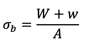
1. Direct stress due to axial load lifted and weight of the rope
Let
W = Load lifted
w = Weight of the rope
A = Net cross-sectional area of the rope
The direct stress is given by
2. Bending stress when the rope winds round the sheave or drum
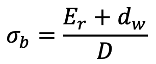
When a wire rope is wound over the sheave, then the bending stresses are induced in the wire which is tensile at the top and compressive at the lower side of the wire. The bending stress induced depends upon many factors such as the construction of rope, size of wire, type of center, and the amount of restraint in the grooves. The approximate value of the bending stress in the wire as proposed by Reuleaux, is
and equivalent bending load on the rope,

Er = Modulus of elasticity of the wire rope
dw = Diameter of the wire
D = Diameter of the sheave or drum
A = Net cross-sectional area of the rope
It may be noted that Er is not the modulus of elasticity for the wire material, but it is of the entire rope. The value of Er may be taken as 77 kN/mm2 for wrought iron ropes and 84 kN/mm2 for steel ropes.
It has been found experimentally that Er = 3/8 E, where E is the modulus of elasticity of the wire material.
If σb is the bending stress in each wire, then the load on the whole rope due to bending may be obtained from the following relation, i.e.

where n is the total number of wires in the rope section.
3. Stresses during starting and stopping
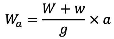
During starting and stopping, the rope and the supported load are to be accelerated. This induces additional load in the rope which is given by
and the corresponding stress,
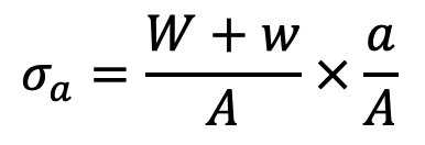
where
a = Acceleration of the rope and load
g = Acceleration due to gravity
If the time (t) necessary to attain a speed (v) is known, then the value of ‘a’ is given by
a = v / 60 t
The general case of starting is when the rope has a slack (h) which must be overcome before the rope is taut and starts to exert a pull on the load. This induces an impact load on the rope.
The impact load on starting may be obtained by the impact equation, i.e.

and velocity of the rope (vr) at the instant when the rope is taut,

Where
a = Acceleration of the rope and Load
h = Slackness in the rope
l = Length of the rope
When there is no slackness in the rope, then h = 0 and vr = 0, therefore
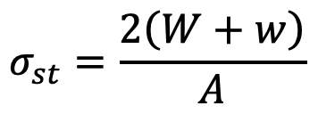
Impact load during starting,
Wst = 2(W+w)
and the corresponding stress,
4. Stresses in wire ropes due to change in speed
The additional stress due to a change in speed may be obtained in a similar way as discussed above in which the acceleration is given
a = (v2 – v1) / t
where (v2 – v1) is the change in speed in m/s and t is the time in seconds.
It may be noted that when the hoist drum is suddenly stopped while lowering the load, it produces a stress that is several times more than the direct or static stress because the kinetic energy of the moving masses is suddenly made zero. This kinetic energy is absorbed by the rope and the resulting stress may be determined by equating the kinetic energy to the resilience of the rope. If during stopping, the load moves down a certain distance, the corresponding change of potential energy must be added to the kinetic energy. It is also necessary to add the work of stretching the rope during stopping, which may be obtained from the impact stress.
5. Effective stress
The sum of the direct stress (σd) and the bending stress (σb) is called the effective stress in the rope during normal working. Mathematically,
Effective stress in the rope during normal working = σd + σb
Effective stress in the rope during the starting = σst + σb
and effective stress in the rope during the acceleration of the load = σd + σb + σa
While designing a wire rope, the sum of these stresses should be less than the ultimate strength divided by the factor of safety.
These are the different stresses in Wire Ropes.
Procedure for Designing a Wire Rope
The following procedure may be followed while designing a wire rope.
1. First of all, select a suitable type of rope from the following tables for the given application.
Table: Steel wire ropes for haulage purposes in mines.
| Type of rope | Nominal diameter (mm) | Average weight (N/m) | Tensile strength (N) | |
| Tensile strength of wire | ||||
| 1600 MPa | 1800 MPa | |||
| 6×7 | 8, 9, 10, 11, 12, 13, 14, 16 18, 19, 20, 21, 22, 24, 25 26, 27, 28, 29, 31, 35 | 0.0347 d2 | 530 d2 | 600 d2 |
| 6 × 19 | 13, 14, 16, 18, 19, 20, 21 22, 24, 25, 26, 28, 29, 32 35, 36, 38 | 0.0363 d2 | 530 d2 | 595 d2 |
Table: Steel wire suspension ropes for lifts, elevators, and hoists.
| Type of rope | Nominal diameter (mm) | Average weight (N/m) | Tensile strength (N) | |
| Tensile strength of wire | ||||
| 1100–1250 MPa | 1250–1400 MPa | |||
| 6 × 19 | 6, 8, 10, 12, 14, 16 18, 20, 22, 25 | 0.0383 d2 | 385 d2 | 435 d2 |
| 8 × 19 | 8, 10, 12, 14,16 18, 20, 22, 25 | 0.034 d2 | 355 d2 | 445 d2 |
Table: Steel wire ropes used in oil wells and oil well drilling
| Type of rope | Nominal diameter (mm) | Approximate weight (N/m) | Ultimate tensile strength (N) | ||
| Tensile strength of wire | |||||
| 1600 – 1800 MPa | 1800 – 2000 MPa | 2000 – 2250 MPa | |||
| 6×7 | 10, 11, 13, 14, 16, 19, 22, 25 | 0.037 d2 | 550 d2 | 610 d2 | – |
| 6 × 19 | 13, 14, 16, 19 22, 25, 29, 32, 35, 38, | 0.037 d2 | 510 d2 | 570 d2 | 630 d2 |
| 6 × 37 | 13, 14, 16, 19, 22, 25, 26, 32, 35, 38 | 0.037 d2 | 490 d2 | 540 d2 | 600 d2 |
| 8 × 19 | 13, 14, 16, 19, 22, 25, 29 | 0.0338 d2 | – | 530 d2 | – |
Table: Steel wire ropes for general engineering purposes such as cranes, excavators etc
| Type of rope | Nominal diameter (mm) | Approximate weight (N/m) | Average tensile strength (N) | ||
| Tensile strength of wire | |||||
| 1600 – 1750 MPa | 1750 – 1900 MPa | ||||
| 6 × 19 | 8, 9, 10, 11, 12, 13, 14, 16, 18, 20, 22, 24, 26, 28, 32, 36, 38, 40 | 0.0375 d2 | 540 d2 | 590 d2 | |
| 6 × 37 | 8, 9, 10, 11, 12, 13, 14 16, 18, 20, 22, 24, 26, 28, 32, 36, 40, 44, 48, 52, 56 | 0.038 d2 | 510 d2 | 550 d2 | |
2. Find the design load by assuming a factor of safety 2 to 2.5 times the factor of safety given in the following Table.
| Application of wire rope | Factor of safety | Application of wire rope | Factor of safety |
| Track cables Guys Mine hoists: Depths up to 150 m 300 – 600 m 600 – 900 m over 900 m Miscellaneous hoists | 4.2 3.58 7 6 5 5 | Derricks Haulage ropes Small electric and air hoists Overhead and gantry cranes Jib and pillar cranes Hot ladle cranes Slings | 6 6 7 6 6 8 8 |
3. Find the diameter of wire rope (d) by equating the tensile strength of the rope selected to the design load.
4. Find the diameter of the wire (dw) and the area of the rope (A) from the following Table.
| Type of wire rope | 6 × 8 | 6 × 19 | 6 × 37 | 8 × 19 |
| Wire diameter (dw) | 0.106 d | 0.063 d | 0.045 d | 0.050 d |
| Area of wire rope (A) | 0.38 d2 | 0.38 d2 | 0.38 d2 | 0.35 d2 |
- Find the various stresses (or loads) in the rope as discussed above.
- Find the effective stresses (or loads) during normal working, during starting, and during acceleration of the load.
- Now find the actual factor of safety and compare it with the factor of safety given in the above factor of safety table If the actual factor of safety is within permissible limits, then the design is safe.
This is How we can Calculate Stresses in Wire Ropes. Let us know what you think about this article in the comment section below.

Leave a Reply