In the previous article, We have discussed how to calculate the shaft diameter under twisting and bending moment with the fluctuating load. In some cases such as propeller shafts of ships, there will be an additional axial load that will act on the shaft in addition to the Torsion and bending loads. Now let us see how we can calculate Shaft Diameter under Axial Load in addition to Torsion and bending loads.

Calculate Propeller Shaft Diameter Under Axial Load
As we have mentioned above the axial load will occur in the propeller shafts of ships and shafts for driving worm gears, then the stress due to axial load must be added to the bending stress (σb).
From the bending equation

Where
M = Bending Moment
I = Moment of inertia of the shaft
σb = Bending stress
y = Distance of the point from the neutral axis = d/2
E = Modulus elasticity of the material
R = Radius of curvature
From this, we can consider the following portion of the equation
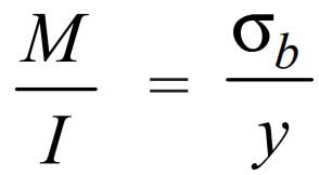
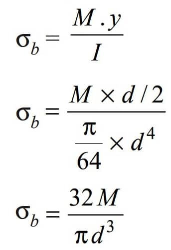
For Solid Shafts
We can rewrite the above equation as follows for the solid shaft.
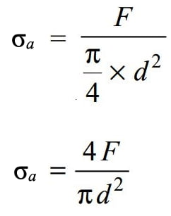
The stress due to axial load for the solid shaft we can write as
The Resultant stress (tensile or compressive) for solid shaft we can write
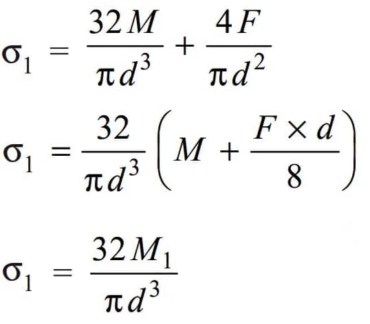
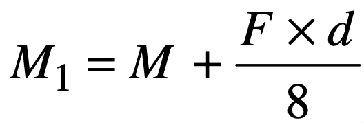
Where we have substituted the M1 value given below
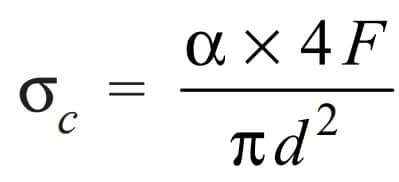
The shafts subjected to axial loads sometimes could be very long shafts such as the propeller shafts and intermediate shafts. In the case of long shafts (slender shafts) subjected to compressive loads, a factor known as column factor (α) must be introduced to take the column effect into account.
The Stress due to the compressive load,
The Column factor (α) for compressive loads may be obtained from the following relation

Where
L = Length of the shaft between the bearings
K = Least radius of gyration
This expression is used when the slenderness ratio (L/K) is less than 115. When the slenderness ratio (L/K) is more than 115, then the value of the column factor may be obtained from the following relation
Column factor formula, if the slenderness ratio (L/K) greater than 115 will be
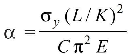
Where
σy= Compressive yield point stress of shaft material
C = Coefficient in Euler’s formula depending upon the end conditions
The following are the different values of C depending upon the end conditions.
| C value | Used for |
| 1 | for hinged ends |
| 2.25 | for fixed ends |
| 1.6 | for ends that are partly restrained as in bearings |
For Hallow Shafts
Similar to the solid shaft, the Bending stress from the bending equation will be

Where
k = di / do
do = Outer diameter of the shaft
di = Inter Diameter of the Shaft
The stress due to axial load for the hollow shaft we can write as
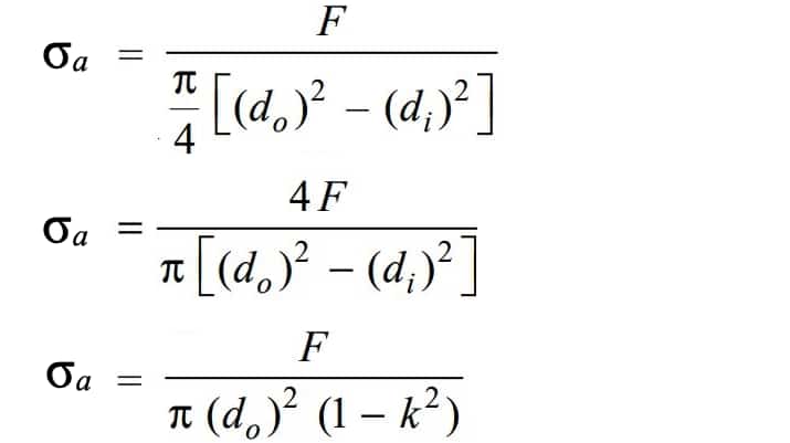
The Resultant stress (tensile or compressive) for hallow shaft we can write
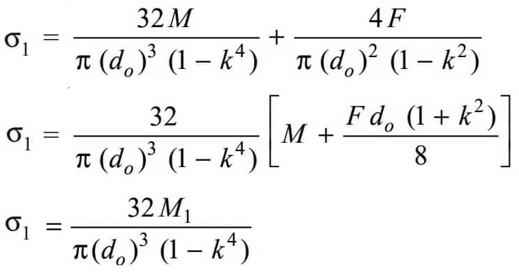
Where we have substituted the M1 value given below

In general, for a hollow shaft subjected to fluctuating torsional and bending load, along with an axial load, the equations for an equivalent twisting moment (Te) will be written as

and equivalent Bending moment (Me) with the additional Axial Load will be written as

We can also write the above twisting moment and the bending moment equations for the solid shafts.
For a solid shaft, k = 0 and d0 = d.
When the shaft carries no axial load, then F = 0
when the shaft carries an axial tensile load, then α = 1
From the above relation, we can calculate the shaft diameter if the shaft is under axial load in addition to the bending and twisting moments.
Let us solve an example problem to calculate the shaft Diameter under axial load in addition to the bending and twisting moments.
Example Problem to Calculate Shaft Diameter under Axial Load
A Propeller solid shaft of 1.5 meters length is supported by the bearing is subjected to a maximum torque of 500 N-m and a maximum bending moment of 1 kN-m. It is subjected, at the same time, to an axial load of 10 kN. Assume that the load is applied gradually. The given permissible shear stress for the shaft material is 40MPa. Calculate the propeller shaft Diameter.
Answer:
Twisting moment T = 500 N-m = 500 × 103 N-mm
Bending moment M = 1 kN-m = 1000 × 103 N-mm
Axial Load F = 10 kN = 10 × 103 N
Permissible shear stress τ = 40MPa = 40 N/mm2
Length of the shaft L =1.5m = 1500mm
Let d = diameter of the propeller shaft (solid shaft)
Since the load is applied gradually, therefore from the table mentioned here, we find that Km = 1.5; and Kt = 1.0 (In most cases these values will be mentioned in the problem itself)
We know that the equivalent twisting moment for a hollow shaft

First, we need to calculate the Slenderness ratio.

Where
L = Length of the shaft between the bearings = 3 meters = 3000mm
K = Least radius of gyration = √(area moment of inertia/ Cross sectional Area)
K = √((π/64)d4/√(π/4)d2 = √0.0625d2 = 0.25d
We substitute the value of K, L we get α = d / (d-0.0264)
For a solid shaft, k = 0 and d0 = d.
From the above, we substitute all the values we have in the equivalent twisting moment equation,


Solving this above equation with the trial and error method will get us the approximate diameter value of 61mm.
To simplify this above calculation process, we can find the least critical shaft diameter by using the following Te formula used for the shaft subjected to fluctuating and twisting and bending together.

From this we can Te = 1581139, Equate this to the above 7.854 × d3
1581139 = 7.854 × d3
d3 = 201316.4
d = 58.60mm
Which is the least critical shaft diameter and choose the next bigger shaft diameter from the diameters of the standard shafts.
This process has to be checked with the bending moment formula also and take the largest shaft diameter among the calculated shaft diameters.

Leave a Reply