The hydraulic machines, which convert the hydraulic energy into mechanical energy, are called turbines while the hydraulic machines which convert mechanical energy into hydraulic energy are called pumps. Hydraulic energy is in the form of pressure energy. If the mechanical energy is converted into pressure energy by means of centrifugal force acting on the fluid, the hydraulic machine is called a centrifugal pump. If the mechanical energy is converted into hydraulic energy (or pressure energy) by sucking the liquid into a cylinder in which a piston is reciprocating (moving backwards and forwards), which exerts the thrust on the liquid and increases its hydraulic energy (pressure energy), the pump is known as the reciprocating pump. Let us discuss how to calculate Work done, power and Discharge through Reciprocating Pump.
Reciprocating Pump
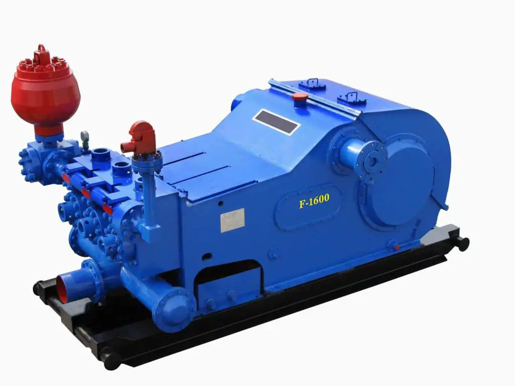
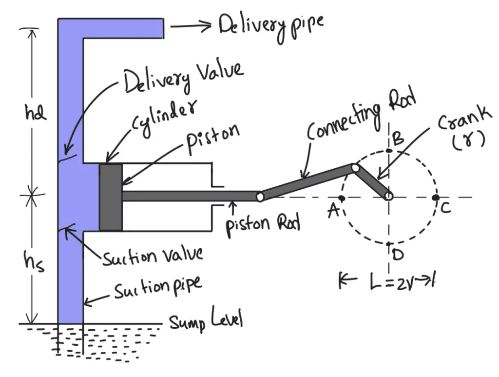
A Reciprocating pump consisting of a piston which moves forwards and backwards in a close-fitting cylinder. The movement of the piston is obtained by connecting the piston rod to the crank by means of a connecting rod.
- The crank is rotated by means of an electric motor.
- Suction and delivery pipes with suction valve and delivery valve are connected to the cylinder.
- The suction and delivery valves are one-way valves or non-return valves, which allow the water to flow in one direction only.
- The suction valve allows water from the suction pipe to the cylinder which the delivery valve allows water from the cylinder to the delivery pipe only.
- When the crank starts rotating, the piston moves to and fro in the cylinder.
- When the crank is at A, the piston is at the extreme left position in the cylinder.
- As the crank is rotating from A to C, (i.e., from θ = 0° to θ = 180°), the piston is moving towards the right in the cylinder.
- The movement of the piston towards the right creates a partial vacuum in the cylinder.
- But on the surface of the liquid in the sump atmospheric pressure is acting, which is more than the pressure inside the cylinder.
- Thus, the liquid is forced into the suction pipe from the sump. This liquid opens the suction valve and enters the cylinder.
- When the crank is rotating from C to A (i.e., from θ = 180° to θ = 360°), the piston from its extreme right position starts moving towards left in the cylinder.
- The movement of the piston towards the left increases the pressure of the liquid inside the cylinder more than atmospheric pressure.
- Hence suction valve closes and the delivery valve opens. The liquid is forced into the delivery pipe and is raised to the required height.
Discharge Through a Reciprocating Pump
Consider a single-acting reciprocating pump as shown in the following figure
Let
D = Diameter of the cylinder
A = Cross-sectional area of the piston or cylinder
r = Radius of crank
N = r.p.m. of the crank
L = Length of the stroke = 2 × r
hs = Height of the axis of the cylinder from the water surface in the sump.
hd = Height of delivery outlet above the cylinder axis (also called the delivery head)
The volume of water delivered in one revolution or discharge of water in one revolution
= Area × Length of stroke
= A × L
Number of revolution per second = N / 60
Discharge of the pump per second Q = Discharge in one revolution × No. of revolution per second
= A × L × N / 60
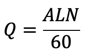
…. Equation (a)
Weight of water delivered per second
W = ρ × g × Q
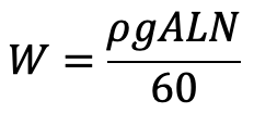
…. Equation (b)
Work done by Reciprocating Pump
Work done by the reciprocating pump per second is given by the reaction as
Work done per second = Weight of water lifted per second × Total height through which water is lifted
Work done = W × (hs + hd)
where (hs + hd) = Total height through which water is lifted.
From equation (b), the Weight W is given by
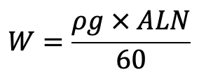
Substituting the value of W in the above equation, we get

…. Equation (c)
Power required to drive the pump, in kW
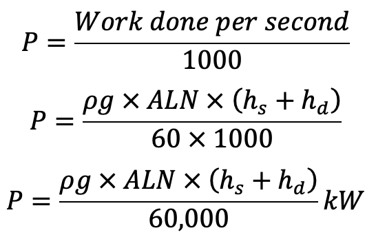
…. Equation (d)
This work done and the power equations we have derived are for the single-acting cylinder Reciprocating pump. How about the double-acting Reciprocating Pump? Let us discuss the Discharge, Work done and the power required to drive the double-acting Reciprocating Pump.
Double-acting Reciprocating Pump
case of a double-acting pump, the water is acting on both sides of the piston as shown in the following schematic diagram.
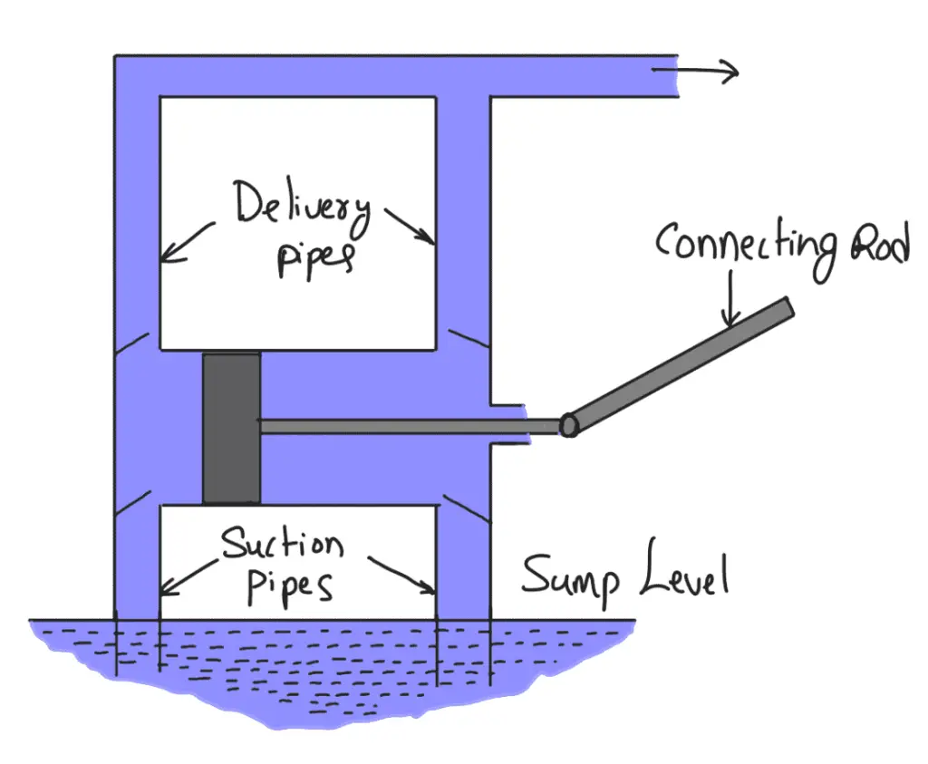
Thus, we require two suction pipes and two delivery pipes for the double-acting pump. When there is a suction stroke on one side of the piston, there is at the same time a delivery stroke on the other side of the piston. Thus for one complete revolution of the crank, there are two delivery strokes and water is delivered to the pipes by the pump during these two delivery strokes.
Discharge Through Double-acting Reciprocating Pump
Let
D = Diameter of the piston
d = Diameter of the piston rod
The area on one side of the piston

The area on the other side of the piston, where the piston rod is connected to the piston
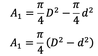
The volume of water delivered in one revolution of the crank
= A × Length of stroke + A1 × Length of stroke
= AL +A1L
= (A + A1)L

Discharge of pump per second = Volume of water delivered in one revolution × No. of revolution per second

If ‘d’ the diameter of the piston rod is very small compared to the diameter of the piston, then it can be neglected and the discharge of the pump per second is
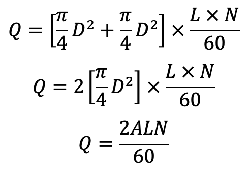
…. Equation (e)
Equation (e) gives the discharge of a double-acting reciprocating pump.
From equation (a) and Equation (e), we understand that the discharge of the double-acting reciprocating pump is two times the discharge of a single-acting pump.
Work done by Double-acting Reciprocating Pump
Work done per second = Weight of water delivered × Total height
= ρg × Discharge per second × Total height
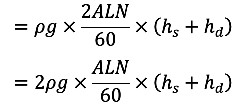
…. Equation (f)
Power required to drive the Double-acting Pump
Power required to drive the double-acting Reciprocating Pump in kW,
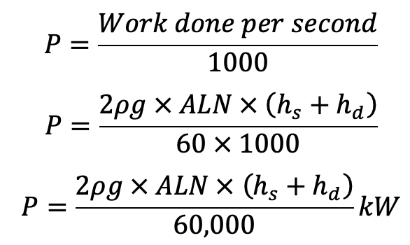
…. Equation (g)
Do you know what is the Slip of Reciprocating Pump?
The slip of a pump is defined as the difference between the theoretical discharge and the actual discharge of the pump. The discharge of a single-acting pump given by equation (a) and of a double-acting pump given by equation (e) are theoretical discharges. The actual discharge of a pump is less than the theoretical discharge due to leakage. The difference between the theoretical discharge and actual discharge is known as the slip of the pump.
Similarly, there are chances the actual discharge is more than the theoretical discharge, and the slip of the pump will become -ve. In that case, the slip of the pump is known as a Negative slip for the Reciprocating Pump. A negative slip occurs when the delivery pipe is short, the suction pipe is long and the pump is running at high speed.
Slip of Reciprocating Pump
The difference between the theoretical discharge and actual discharge is known as the slip of the pump.
Hence, mathematically
Slip = Qth– Qact
But slip is mostly expressed as percentage slip which is given by
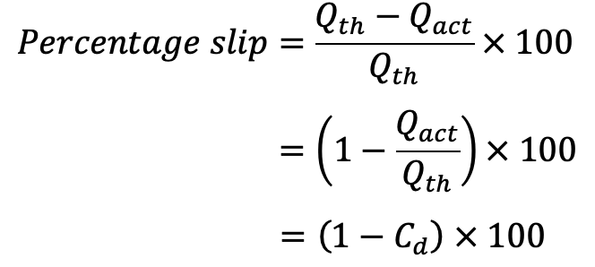
where Cd = Co-efficient of discharge.
Let us solve an example problem on Discharge, and the slip of the Reciprocating Pump.
Example Problems on Reciprocating Pump
Problem Statement: A single-acting reciprocating pump, running at 50 r.p.m., delivers 0.01 m3/s of water. The diameter of the piston is 200mm and the stroke length is 400mm.
Determine:
(i) The theoretical discharge of the pump
(ii) Co-efficient of discharge
(iii) Slip and the percentage slip of the pump.
Answer:
Speed of the pump, N = 50 r.p.m
Actual discharge Qact = 0.01 m3/s
Diameter of the Piston D = 200mm = 0.20 m
Area A = (π/4) (0.2)2 = 0.31416 m2
Stroke L = 400mm = 0.4 m
The Theoretical discharge for a single-acting reciprocating pump is given by equation (a) is given by

Co-efficient of discharge is given by

Using Slip of the reciprocating pump equation, we get
Slip = Qth– Qact
Slip = 0.01047 – 0.01
Slip = 0.00047m3/s
And percentage slip

This is how you can calculate the Slip, and Discharge through Reciprocating Pump. Let us know what you think about this article in the comment section below.

Leave a Reply