The hydraulic machines, which convert the hydraulic energy into mechanical energy, are called turbines while the hydraulic machines which convert mechanical energy into hydraulic energy are called pumps. Hydraulic energy is in the form of pressure energy. If the mechanical energy is converted into pressure energy by means of centrifugal force acting on the fluid, the hydraulic machine is called a centrifugal pump. Let us discuss more details of the Centrifugal Pump such as its construction, its main parts, how the Centrifugal Pump works and the Multistage Centrifugal Pumps.

Centrifugal Pump
As we mentioned Centrifugal Pump converts the mechanical energy into pressure energy by means of centrifugal force acting on the fluid.
- The centrifugal pump acts as a reverse of an inward radial flow reaction turbine.
- This means that the flow in centrifugal pumps is in the radial outward directions.
- The centrifugal pump works on the principle of forced vortex flow.
- This means that when a certain mass of liquid is rotated by an external torque, the rise in pressure head of the rotating liquid takes place.
- The rise in pressure head at any point of the rotating liquid is proportional to the square of the tangential velocity of the liquid at that point.
- Thus at the outlet of the impeller, where the radius is more, the rise in pressure head will be more and the liquid will be discharged at the outlet with a high-pressure head.
- Due to this high-pressure head, the liquid can be lifted to a high level.
Centrifugal Pump Main Parts
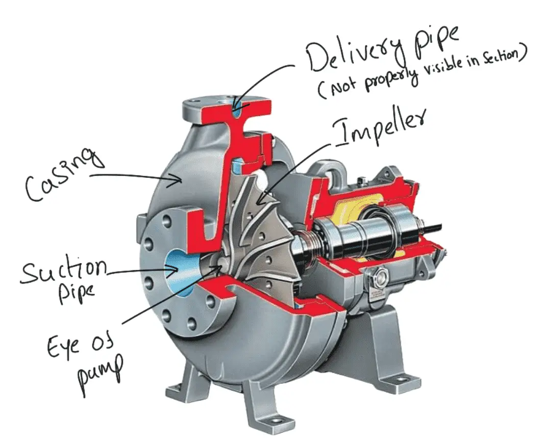
Centrifugal Pump has the following main parts.
- Impeller
- Casing
- Suction pipe with a foot valve and a strainer
- Delivery pipe
1. Impeller
The rotating part of a centrifugal pump is called an ‘impeller’. It consists of a series of backwards-curved vanes. The impeller is mounted on a shaft which is connected to the shaft of an electric motor.
2. Casing
The casing of a centrifugal pump is similar to the casing of a reaction turbine. It is an air-tight passage surrounding the impeller and is designed in such a way that the kinetic energy of the water discharged at the outlet of the impeller is converted into pressure energy before the water leaves the casing and enters the delivery pipe. The following three types of the casings are commonly adopted:
(a) Volute casing
(b) Vortex casing
(c) Casing with guide blades
(a) Volute Casing
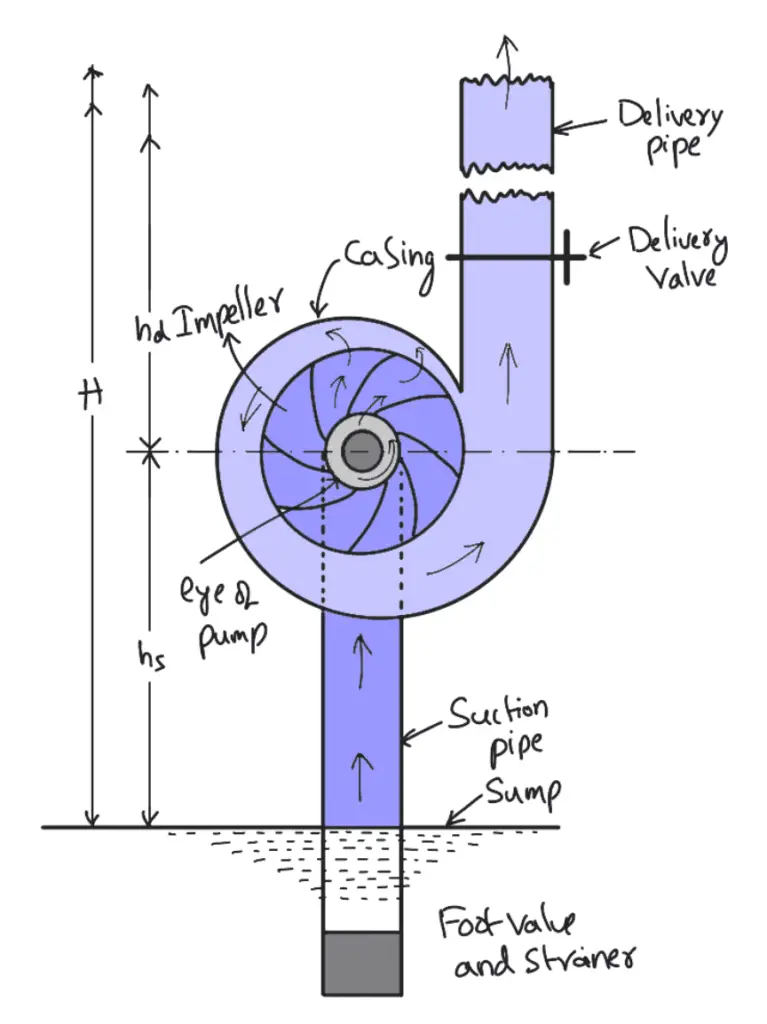
The following Figure shows the volute casing, which surrounds the impeller. It is of a spiral type in which the area of flow increases gradually. The increase in the area of flow decreases the velocity of flow. The decrease in velocity increases the pressure of the water flowing through the casing. It has been observed that in the case of the volute casing, the efficiency of the pump increases slightly as a large amount of energy is lost due to the formation of eddies in this type of casing.
(b) Vortex Casing
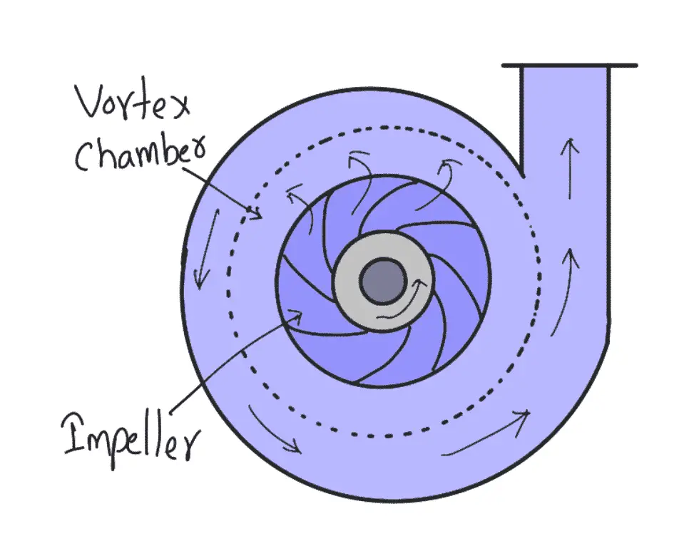
If a circular chamber is introduced between the casing and the impeller as shown in the above schematic diagram, the casing is known as Vortex Casing. By introducing the circular chamber, the loss of energy due to the formation of eddies is reduced to a considerable extent. Thus the efficiency of the pump is more than the efficiency when only volute casing is provided.
(c) Casing with Guide Blades
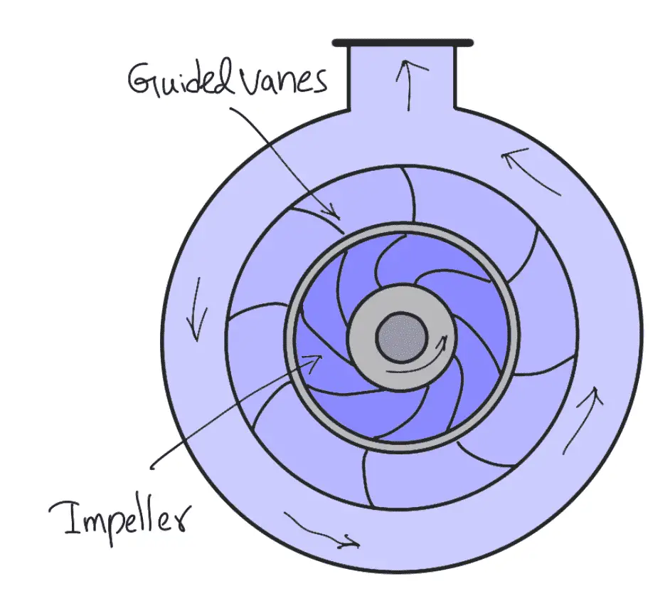
This casing is shown in the above schematic diagram in which the impeller is surrounded by a series of guide blades mounted on a ring which is known as a diffuser. The guide vanes are designed in such a way that the water from the impeller enters the guide vanes without stock. Also, the area of the guide vanes increases, thus reducing the velocity of flow through guide vanes and consequently increasing the pressure of water. The water from the guide vanes then passes through the surrounding casing which is in most of cases concentric with the impeller as shown in the above schematic diagram.
3. Suction Pipe with a Foot valve and a Strainer
A pipe whose one end is connected to the inlet of the pump and another end dips into water in a sump is known as a suction pipe. The Afoot valve which is a non-return valve or one-way type of valve is fitted at the lower end of the suction pipe. The foot valve opens only in the upward direction. A strainer is also fitted at the lower end of the suction pipe.
4. Delivery Pipe
A pipe whose one end is connected to the outlet of the pump and the other end delivers the water at a required height is known as a delivery pipe.
Multistage Centrifugal Pumps
If a centrifugal pump consists of two or more impellers, the pump is called a multistage centrifugal pump. The impellers may be mounted on the same shaft or on different shafts. A multistage pump is having the following two important functions:
- To produce a high head
- To discharge a large quantity of liquid
If a high head is to be developed, the impellers are connected in series (or on the same shaft) while
for discharging large quantities of liquid, the impellers (or pumps) are connected in parallel.
1. Multistage Centrifugal Pumps for High Heads
For developing a high head, a number of impellers are mounted in series or on the same shaft as shown in the following schematic diagram.
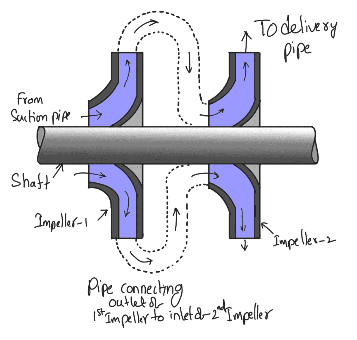
The water from the suction pipe enters the 1st impeller at the inlet and is discharged at the outlet with increased pressure. The water with increased pressure from the outlet of the 1st impeller is taken to the inlet of the 2nd impeller with the help of a connecting pipe as shown in The above schematic diagram. At the outlet of the 2nd impeller, the pressure of water will be more than the pressure of water at the outlet of the 1st impeller. Thus if more impellers are mounted on the same shaft, the pressure at the outlet will be increased further.
Let
n = Number of identical impellers mounted on the same shaft
H = Head developed by each impeller
The total head developed = n × Hm
The discharge passing through each impeller is the same
2. Multistage Centrifugal Pumps for High Discharge
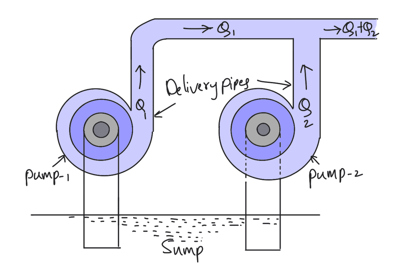
For obtaining a high discharge, the pumps should be connected in parallel as shown in the above schematic arrangement. Each of the pumps lifts the water from a common pump and discharges water to a common pipe to which the delivery pipes of each pump are connected. Each of the pumps is working against the same head.
Let,
n = Number of identical pumps arranged in parallel
Q = Discharge from one pump
Total discharge = n × Q
This is all about the Centrifugal Pump. Let us know what you think about this article in the comment section. Check out the Comparison of the Centrifugal Pump with the Reciprocating Pump.

Informative post, Sundar! I particularly liked the description of the casing which is a significant part of a centrifugal pump. It’s true that here, the kinetic energy of the water discharged at the outlet turns into pressure before the water flows out. So, it’s important to make the casing strong and reliable which can be done through forging.