We have been discussing the different types of Cotter joint, and in the previous article, we have discussed how to design the Gib and cotter joint for the connecting rod big end with strap. In this article, we are going to design a Cotter joint to connect piston rod and crosshead.

Cotter Joint to Connect Piston Rod and Crosshead
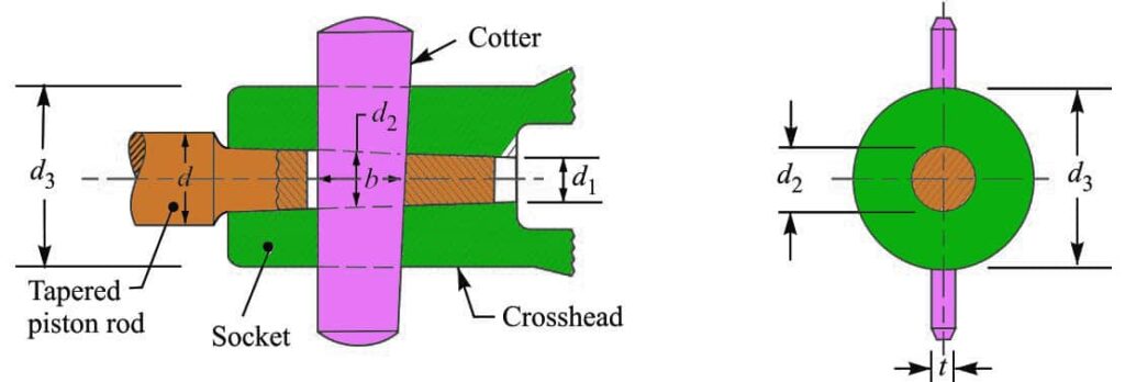
Following is the cotter joint which is used to connect the Piston rod and Crosshead. The piston rod is tapered in order to resist the thrust. The taper we can use for the piston rod may be from 1 in 24 to 1 in 12.

The piston rod and crosshead may be subjected to a tensile or compressive load. All components of the joint are assumed to be of the same material.
Let us assume
d = Diameter of parallel part of the piston rod,
d1 = Diameter at the tapered end of the piston,
d2 = Diameter of piston rod at the cotter,
d3 = Diameter of the socket through the cotter hole,
b = Width of cotter at the center,
t = Thickness of cotter,
σt = Permissible tension stress
τ = Permissible shear stress
σc = Permissible crushing stress
We know that maximum load on the piston,
P = (π/4) × d2 × p
where
D = Diameter of the piston, and
p = Effective steam pressure on the piston.
In designing a cotter joint to connect Piston rod and crosshead, the following modes of failure may occur. Or at least we need to consider these failures in order to determine the design parameters of the Cotter joint to connect Piston rod and Crosshead.
- Failure of piston rod in tension at cotter
- Failure of cotter in shear
- Failure of the socket in tension at cotter
- Failure of socket in crushing
1. Piston Rod Diamter
The piston rod diameter can be determined by assuming the Failure of the piston rod in tension at the cotter.
The piston rod may fail in tension at the cotter due to the maximum load on the piston. We know that area resisting tearing at the cotter will be

The Tearing strength of the piston rod at the cotter will be the product of the cross-section area that resists the tensile stress and the induced tensile stress.

Let us equate the tearing strength to the maximum load (P), we can write

From this relation, we can determine the diameter of the piston rod at the cotter (d2).
The thickness of cotter (t) is taken as 0.3 d2.
2. Width of the Cotter
By assuming the Failure of the cotter in shear, we can obtain the width of the Cotter.

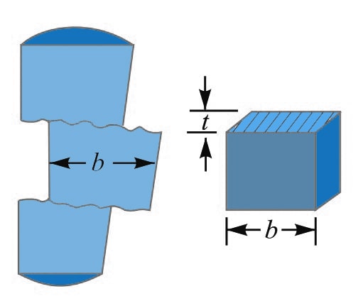
As you can see the above schematic representation of the Cotter being pulled away by the two equal opposite loads results in double shear.
The shearing area of the cotter will
= 2 b × t
and shearing strength of the cotter will be the product of the permissible shear stress of the
= 2 b × t × τ
Now equate this relation to the load (P), we can write as
P = 2 b × t × τ
From this relation, we can determine the width of cotter (b).
3. Diameter Of Socket (d3)
By considering the Failure of the socket in tension at the cotter, we can determine the Diameter Of the Socket.
We know that area that resists the tearing of the socket at the cotter is

and the tearing strength of the socket at the cotter will be the product of the area that resists the tearing of the socket at the cotter and the induced tensile stress. we can write the relation as follows.

Equating this to maximum load (P), we have

From this equation, the diameter of the socket (d3) is obtained.
4. Induced Crushing Stress In The Socket
The induced crushing stress in the socket may be checked by considering the Failure of the socket in crushing.
We know that area that resists crushing of socket
= (d3 – d2) t
and crushing strength of the socket
= (d3 – d2) t × σc
Equating this to maximum load (P), we have
P = (d3 – d2) t × σ
From this relation, the induced crushing stress in the socket may be checked.
The length of the tapered portion of the piston rod (L) is taken as 2.2 d2.
The diameter of the parallel portion of the piston rod (d) = d2 + (L/2) × Taper
The diameter of the piston rod at the tapered end (d1) = d2 – (L/2) × Taper
By the way, the taper on the piston rod is usually taken as 1 in 20. from this also the d1 can be obtained.
Let us solve a sample problem to design a Cotter Joint to Connect Piston Rod and Crosshead.
Example Problem Statement
Design a cotter joint to connect the piston rod to the crosshead of a double-acting steam engine. The diameter of the cylinder is 300 mm and the steam pressure is 1 N/mm2. The allowable stresses for the material of the cotter and piston rod are as follows.
σt = 50 MPa
τ = 40 MPa
σc = 84 MPa
Answer:
Given data:
Cylinder diameter (D) = 300 mm
Steam pressure inside cylinder (p) = 1 N/mm2
(σt= 50 MPa = 50 N/mm2
(τ) = 40 MPa = 40 N/mm2
σc= 84 MPa = 84 N/mm2
We know that maximum load on the piston rod,
P = (π/4) × d2 × p = (π/4) × (300)2 × 1 = 70695N
The various dimensions for the cotter joint to connect Piston rod and crosshead of the double-acting steam engine are obtained by considering the different modes of failure as mentioned above.
1. Diameter of piston rod at cotter
Let us say
d2 = Diameter of piston rod at cotter, and
t = Thickness of cotter. It may be taken as 0.3 d2.
Considering the failure of the piston rod in tension at the cotter. We know that load (P)

70695 = [(π/4) × (d2)2 – d2 × (0.3 d2)] × 50
70695 = [(π/4) × (d2)2 – 0.3 (d2)2] × 50
70695 = 24.27 (d2)2
(d2)2 = 70 695 / 24.27
(d2)2= 2913
d2 = 53.97
We got the Diameter of the Piston rod at the cotter as 53.97mm, let us take this value as 55mm.
The thickness of the Cotter (t) will be = 0.3 d2 = 0.3 × 55 = 16.5 mm
2. Width of cotter
Let us say b = Width of cotter.
Considering the failure of cotter in shear. Since the cotter is in double shear, therefore load (P),
P = 2 b × t × τ
70695 = 2 b × t × τ
70695= 2 b × 16.5 × 40
70695= 1320 b
b = 70 695 / 1320
b = 53.5
We got the width of the cotter as 53.5mm, let us round it up to 54mm.
3. Diameter of socket
Let us take d3 = Diameter of the socket.
Considering the failure of socket in tension at cotter. We know that load (P),

70695 = [(π/4) {(d3) 2 – 552} – ( d3 – 55) 16.5] 50
70695 = 39.27 (d3) 2 – 118792 – 825 d3 + 45375
(d3) 2 – 21 d3 – 3670 = 0
Solving this equation we algebric equation, we get d3 =73mm.
Let us now check the induced crushing stress in the socket. We know that load (P),
P = (d3 – d2) t × σ
70695 = (d3 – d2) t × σc
70695= (72 – 55) 16.5 × σc
70695= 280.5 σc
σc = 70 695 / 280.5
σc = 252 N/mm
Since the induced crushing is greater than the permissible value of 84 N/mm2, therefore let us find the value of d3 by substituting σc= 84 N/mm2 in the above expression,
P = (d3 – d2) t × σ
70695 = (d3 – 55) 16.5 × 84
70695 = (d3 – 55) 1386
d3 – 55 = 70 695 / 1386
d3 – 55 = 51
d3 = 55 + 51 = 106
The diameter of the socket we get is (d3) 106mm
We know the tapered length of the piston rod is (L) = 2.2 d2 = 2.2 × 55 = 121 mm.
Assuming the taper of the piston rod as 1 in 20, therefore the diameter of the parallel portion of the piston rod is
d = d2 + (L/2) × Taper
d = 55 + (121/2) × (1/20)
d =58mm.
The diameter of the piston rod at the tapered end is
d1 = d2 – (L/2) × Taper
d1 = 55 – (121/2) × (1/20)
d1 = 52mm.
These are all the parameters to design the Cotter Joint to Connect Piston Rod and Crosshead.
How about solving another example problem to connect the Piston rod and Crosshead with a cotter joint?
Design a cotter joint to connect the piston rod to the crosshead of a double-acting steam engine. The diameter of the cylinder is 540 mm and the steam pressure is 2.3 N/mm2. The allowable stresses for the material of the cotter and piston rod are as follows.
σt = 50 MPa
τ = 40 MPa
σc = 60 MPa
Solve this example and let me know the answer in the comment section below.

Leave a Reply