A final year project on “Design Of Solar Powered Quadcopter” submitted by Kolakaluri Daisy (from Velagapudi Ramakrishna Siddhartha Engineering College) to extrudesign.com.
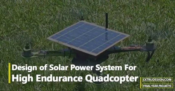
Title: Design Of Solar Power System For A High Endurance Quadcopter
Abstract
Sunlight energy is potentially excellent for small drones, which can often operate during daylight hours and fly high enough to avoid cloud blockade. However, the best solar cells provide limited power, compared to conventional power sources, making their use for aerial vehicles difficult to realize, especially in rotorcraft where significant lift ordinarily generated by a wing is already sacrificed for the ability to hover. In recent years, advances in materials (use of carbon-fibre components, improvement in specific solar cells and motors) have finally brought solar rotorcraft within reach. Here, the application is explored through a concise mathematical model of solar rotorcraft based on solar power generation and motor power consumption limits. Multiple solar quadcopters based on this model with majority solar power are described. One of them has achieved outdoor airtime over 3 hours, 48 times longer than it can last on just battery alone with the solar cells carried as dead weight and representing a significant prolongation of drone operation. Solar-power fluctuations during a long flight and their interaction with power requirements are experimentally characterized. The general conclusion is that solar cells have reached high enough efficiencies and can outperform batteries under the right conditions for quadcopters.
Best of the conventional Lithium polymer (LiPo) battery packs can offer maximum power backup of 1-2 hours per full recharge, which is inadequate for applications demanding longer flight time (i.e. longer endurance). The Maximum Power Point Tracking (MPPT) charge controller is a DC to DC transformer that can transform power from a higher voltage to power at a lower voltage. Thus the design of UAVs for low altitude high endurance missions requires a robust power backup system. With the above considerations in view, solar-powered quadrotor type UAVs has been identified as a potential solution for the problem under context. However, the design of a solar-powered quadrotor is characterized as a design problem that needs to be customized for the intended application/ mission specifications. The second challenge is that the design of solar-powered UAV is a significant optimization problem mainly in terms of weight-to-power ratio.
Despite the complexity of the design problem, a significant motivation for embarking on the project is that Solar Powered High endurance UAVs of quadrotor type can be effectively used for a range of civilian tasks, such as transportation of critical payload for agriculture, road traffic management, natural calamities etc.
Keywords: Unmanned Aerial Vehicle, Solar Energy, Quadcopter, Environmental Monitoring, Charge Controller, Maximum Power Point Tracking, Solar Powered Quadcopter
Introduction
Nowadays the ability to fly without using conventional fossil fuels is primarily focused in recent years, both application point of view and scientific field since the major concerns are an increase in global warming and a decrease in natural resources. Since then, the use of electric quadcopters has been widespread but here the crucial issue is their high power consumption when compared with their limited energy storage capability, which leads to an endurance that can rarely exceed half an hour. Increasing the size of the battery or incorporating more batteries increases the weight of the plane, which affects the flight time of the UAV as it is inversely proportional. So, now, the ability to fly a quadcopter to increase the endurance limit has been a key issue in both UAVs and civilian aviation.
Quadcopters, as opposed to fixed-wing aerial vehicles, are classified as a type of unmanned aerial vehicle (UAVs) and have been used in many applications, such as environmental monitoring, communication, delivery service, etc., due to their greater manoeuvrability, hovering capability, and low cost. While quadcopters have their obvious advantages in a wide area of applications, existing quadcopter platforms are subject to limited flight duration. Although new techniques for autonomous battery swapping has been developed to resume the UAV flight, it still has flight duration limitations and drastically reduces the mobility of UAVs due to frequent recalls of battery swapping. This paper investigates the feasibility of integrating renewable energy harvesting capabilities into a quadcopter to allow for long-endurance missions with payload requirements.
To extend an aerial vehicle’s operational time has, in large part, focused on the selection of efficient components, energy-optimized system design, and the use of power-efficient path planning. Besides flight duration, the payload capability plays an important role when evaluating the system performance of a quadcopter.
One of the possibilities to increase the flight time is by using unlimited solar energy through solar cells. These cells, by connecting them with an electronic circuit, can provide sufficient power for the motor and the electronics and, if in excess, it can also be stored in the battery; here the battery can be used as a buffer when flying in darkness or under clouds. Hence, the possible solution to enhance the endurance is by using solar-powered quadcopter driven by electric-based propulsion systems in which the power is supplied continuously throughout the day by unlimited solar energy, which can eliminate fuel and also solve the limited energy storage capability problem.
1. Literature Review And Problem Statement
1.1 Classification Of UAVs (Based On Size):
Different UAV classification schemes have been proposed to help differentiate existing systems based on their operational characteristics and their capabilities.
Close range – fly in a range of fewer than 25 km. Usually extremely light;
- Short range – operate within a range of 25-100km.
- Medium range – Able to fly within a range of 100-200km. Need more advanced aerodynamic design and control systems due to their higher operational performance.
- Long range – Fly within a range of 200-500km. Require more advanced technology to carry out complex missions. Need satellite link in order to overcome the communication problem between the ground control systems and quadcopter created by the curvature of the earth.
- Endurance – Operate in a range more than 500km, or can stay in the air for more than 20 hrs. This is considered the most sophisticated of the UAV family due to their high capabilities.
Technologies related to low-altitude long-endurance (LALE), medium-altitude long-endurance (MALE), and high-altitude long-endurance (HALE) unmanned aerial vehicles (UAVs) have recently become crucial due to various desires, including, in particular, internet coverage extension to remote areas having no mobile network coverage. In general, LALE, MALE, and HALE UAVs fly up to 25-100km, between 100-200km, and over 200-500km, separately, and flight time exponentially increases as operation altitude increases. HALE UAVs, for instance, are designed to fly, in theory, indefinitely without any energy source from outside aside from solar power or fuel-cell based on a hydrogen generator. Although MALE and HALE UAVs have advantages in the sense of flight time and energy efficiency, the size of the wingspan is too large to safely operate in an urban area, and the runway is indispensable. Thus, despite the limited flight time, light and small LALE UAVs, instead, are more preferable to safely and freely use in civilian areas complying with legal regulations. Research trends to optimize UAV energy efficiency can be categorized into mainly three: (1) Mission waypoint optimization (MWO), (2) hybrid-electric propulsion systems (HEPS), and (3) effective power management systems (EPMS).
There have been many research-level attempts to develop a small LALE UAV based on a HEPS using a fuel cell (FC), solar cell, and battery pack. In this project research, we are developing a solar cell based LALE UAV and also developed three main systems, including maximum power point tracking (MPPT), a battery management system (BMS), and a power conversion system. Both methods, using the combination of a fuel cell, solar cell, and battery pack or using the combination of solar cell and battery pack, require using a power management system (PMS) to control power flows. In this project, we are working to build a quadcopter type LALE UAV that uses stationary alternating current (AC) loads and requires a long runway and a large area to operate. From this perspective, we will design the tethered multirotor-type LALE UAV swarming system for, ultimately, continuous aerial surveillance without any single human intervention using pure solar energy. Compared to the fixed-wing UAV, the multirotor-type UAV results in much higher magnitude and fluctuation of current and voltage, and the handling technique of this dynamic energy flow is very important to develop the long-endurance multirotor-type UAV. Although the operation range is limited, a tethered multirotor-type LALE UAV could hover for several hours in the air and perform a continuous surveillance mission for the specific area.
1.2 Fixed wing UAV’s Versus Rotor type UAV’S:
Fixed-wing UAVs
Fixed-wing drones will be familiar to everyone since they look like conventional aircraft. There are several different configurations available, but typically they have a fuselage with two wings and a single rotor. Fixed-wing aircraft are most popular in the agricultural and oil and gas industries since they can cover large areas at high speed. They are less common for surveying applications but do have some interesting characteristics that users may find useful.
Multirotor UAVs
These are the most common types of drones available and make up the vast majority of commercial and consumer models available. Many different configurations are available but they generally follow the same design principle. There is a central chassis that connects up to eight fixed-pitched propellers to control the speed, direction and elevation of the aircraft.
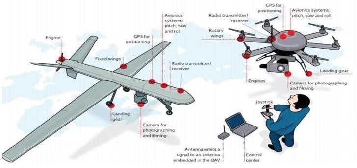
These propellers control the direction and elevation of the aircraft by varying the speed of each propeller to alter the amount of thrust and torque produced. This gives the aircraft a unique set of handling characteristics, allowing it to fly with extreme precision in both enclosed and open space.
The four-propeller multirotor (quadcopter) is the most popular design because it provides the best balance between lift, control, manoeuvrability and cost.
While multirotor drones provide several advantages for surveying compared to fixed-wing aircraft. That doesn’t mean they are the de facto choice for surveying. Operators should review the pros and cons of each before making a final decision.
1.3 Problem statement:
High altitude High endurance Unmanned Aerial Vehicles (UAVs) are fixed-wing type configurations. The fixed-wing type UAVs has usually large wings, typically 4-6m long. Fixed-wing type UAVs are suitable for more than 10Km altitude applications. However, for civilian applications (like surveying, traffic control, material transportation etc.), UAVs need to navigate at altitudes of the order of 10-50m. There are several obstacles at lower altitudes like trees, electric & telephone poles, advertisement hoardings etc. These obstacles render the fixed-wing type UAVs unsuitable for lower altitude applications. In contrast, Quadrotor type UAVs due to their manoeuvrability, smaller size and greater ease of control offers a potential solution for low altitude applications. However, a major challenge with rotor type UAVs is the power source constraint.
2. Design Considerations Of Solar Powered Quadcopter
2.1 Design Methodology
The main principle is to make use of available unlimited solar energy by converting it into electricity through solar cells. When sunlight strikes the solar cell, the cell creates electrons and holes as charge carriers and, when a circuit is made, the free electrons pass through a certain load to recombine with holes and, in this way, the current is generated. Here, by arranging solar cells in series on the top of the quadcopter and then wrapping the top of the quadcopter with transparent material for the safety of solar cells during flight, cells are arranged in series to get the required voltage to safely charge the battery; from there, the battery power is supplied to the motor for throttling during constant level flight. In this, the aircraft was assumed to be a quadcopter, which means it also stores the energy in the battery during the gliding period. In this way, both flying the plane by using solar energy alone and storing the energy in the battery to extend the flight time can be achieved.
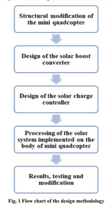
The process flow of designing a solar-powered mini quadcopter is shown in Figure
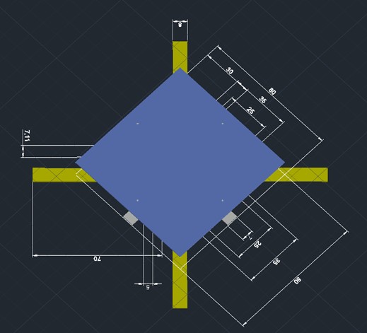
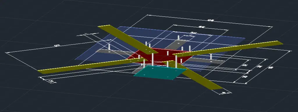
At the very first step, a quadcopter model was chosen for the design & development of the solar power system. Firstly, it is small and lightweight which fulfil the requirement of this project to develop a solar-powered mini drone. Secondly, it is built-in with a first-person-view camera which favours the environmental monitoring tasks as one of the possible future applications. In this step, the position of the solar panel was determined. The modified structure was first drawn using Autocad and the realisation of the designed structure was carried then. Next, the design of the circuitry of the solar boost converter and charge controller was carried out.
Then, the designed solar system was ready in this step and implemented on the body of the mini-drone which was then tested in the final stage. Adjustment and modification were done in the final stage to make the solar power system fully functional enabling the mini drone to perform flight operation.
The design process of the entire quadcopter is composed of two phases: conceptual and preliminary. In conceptual design, the basic configuration arrangement, size, weight, and performance are calculated. Then, designing the CAD modelling of individual parts to meet the required targets and optimizing it are done in preliminary design. The design requirements are used to guide and evaluate the development of the overall quadcopter configuration.
There are two simple balances:
- Weight balance: the lift force has to be equal to the weight of all the elements constituting the airplane.
- Energy balance: the energy that is collected during a day from the solar panel has to be equal to or higher than the electrical energy needed by the airplane during its level flight.
2.2 Structural modification of mini quadcopter
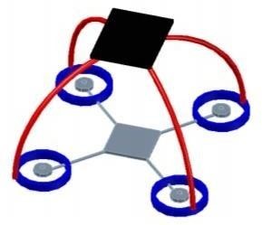
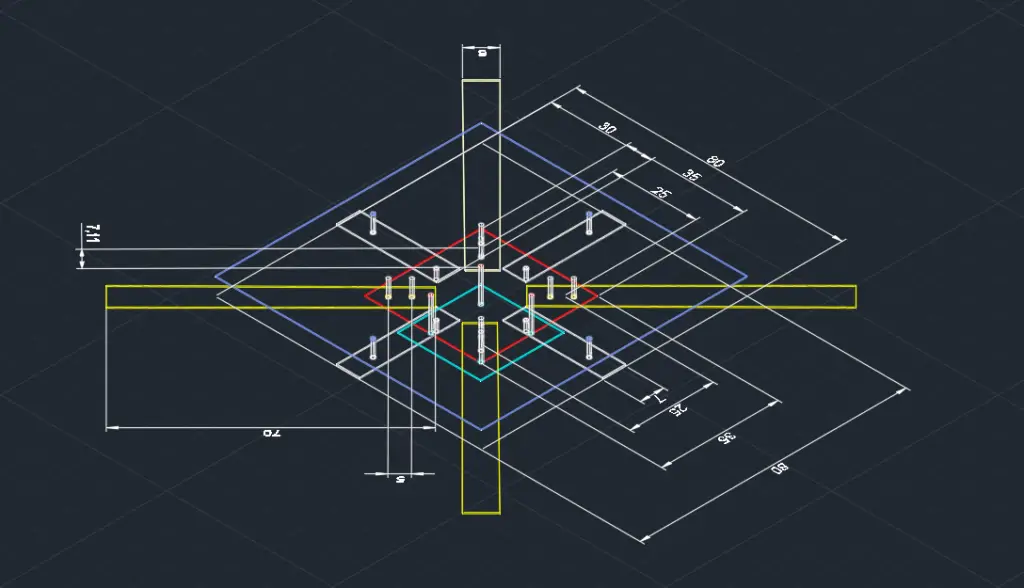
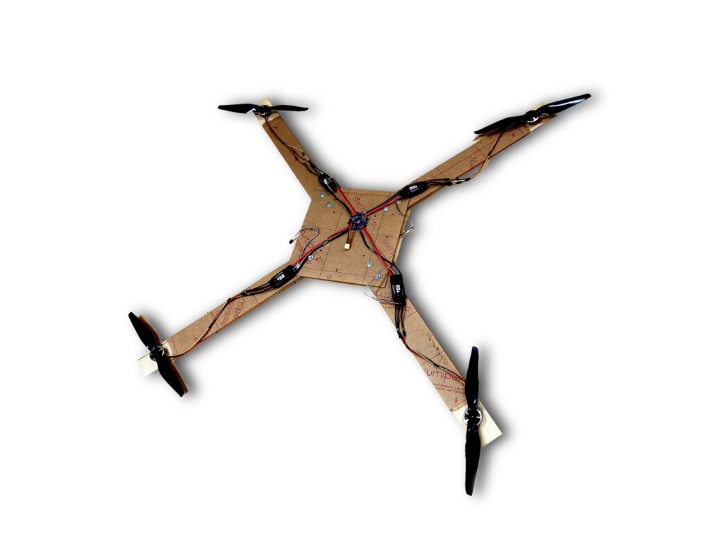
The design and modification of the structure of the mini quadcopter are shown in Figure. The black shape on top represented the solar panel. The placement of the solar panel was located at the best position in the body to get most radiation energy from the sunlight without affecting the aerodynamics of the quadcopter since it was located at the centre of the body. The blue frame which covers each motor was the typical framework provided by a mini drone in the market for outdoor protection. CAD design of structural modification of the mini quadcopter.
When designing the structure of the flying model, firstly lightweight possible structure was considered. This provided an idea to make the added structure as a frame. The wireframe has the advantages of not only lightweight but also bendable which makes modifying the process a lot easier.
2.3 Mission Specifications
One of the main aims of this paper is to check whether the power available from the Sun is required to power a quadcopter, which, in turn, helps in increasing the endurance of the quadcopter from a couple of minutes to hours. Here the gross weight of the plane (2 kg) is kept constant. There was no range requirement since the goal was simply to remain flying, not to reach any destination.
| Parameter | SI units |
| Gross weight | 2 kg |
| Payload | 0.5 kg |
| Altitude | 30 – 50 m |
| Average air density | 1.22 kg∙m-3 |
| Clearness factor | 0.7 (1 = clear sky) |
| Take-off distance | None (hand toss launch) |
2.4 Aerodynamics of the quadcopter
The thrust forces and drag torques produced by the propellers are calculated by considering the blade element theory (BEM), where the thrust force and the pulling torque are expressed from the following way:
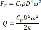
Where,
FT: Thrust force.
Q: Drag torque.
Ct: Thrust coefficient.
Cp: Power coefficient.
ρ: Density of air.
D: Propeller diameter.
ω: Rotation speed of the propeller.
2.5 Theorical model
For the development of the theoretical model notation should be considered:
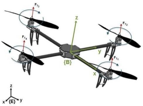
Where;
E: Fixed reference frame. B: Body reference frame.
FTi : propeller thrust force i.
2.6 Solar Powered Quadcopter Circuit Diagram
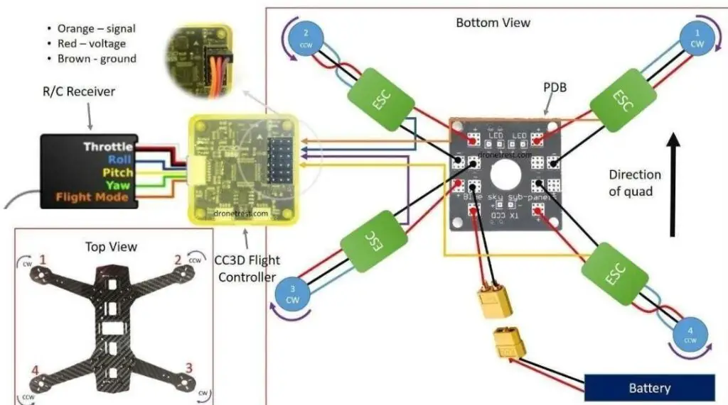
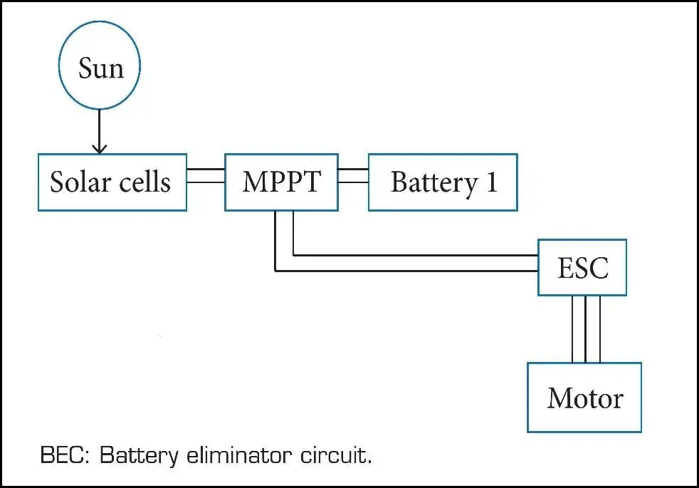
From the circuit diagram, the energy received from the Sun is collected by the solar panel, which converts it into electricity and then there is the maximum power point tracker (MPPT), which helps in tracking the maximum power of any solar cell and provides it at all times. In MPPT, there are 3 terminals: one is connected to the solar panel; the other, to load (motor); and the last one, to the battery. Then, in level flight, the MPPT sends power directly to the motor from the solar cells and, when gliding, as the motor does not require power, the battery starts charging. If an excess of power is required, during climbing or when the solar intensity is low, the battery supplies the required power, which is stored into the motor. Thus, from the battery, the energy goes to the motor, which rotates the propeller and, between them, there is an electronic speed control (ESC) regulating the speed. Besides the present battery, there is an additional small pencil battery to control the avionics; the reason to separate it is, even if there is any problem in the main circuit or else, any damage in the cells still controlling the plane can be done as the control system’s battery is not connected to the main circuit, which helps in a safe landing.
3. Selection Of Components For The Solar Powered Quadcopter
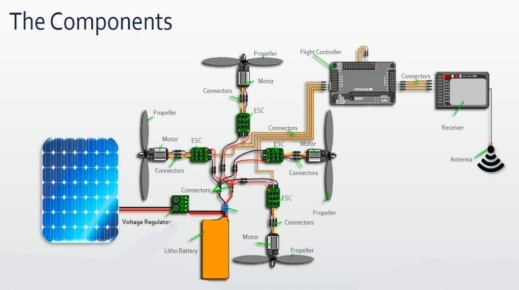
3.1 Selection of Components of the Quadrotor type UAV: Electrical Motors, Propellers, ESC, LiPo Battery
3.2 Brushless DC Electric Motor:
A brushless DC electric motor also known as an electronically commutated motor (ECM or EC motor) and synchronous DC motors, are synchronous motors powered by direct current (DC) electricity via an inverter or switching power supply which produces electricity in the form of alternating current (AC) to drive each phase of the motor via a closed-loop controller. The controller provides pulses of current to the motor windings that control the speed and torque of the motor. This control system replaces the commutator (brushes) used in many conventional electric motors. The advantages of a brushless motor over brushed motors are high power-to-weight ratio, high speed, electronic control, and low maintenance.
BLDC motors are used in Quadcopters. These motors consist of a permanent magnet that rotates around a fixed armature. They offer several advantages over brushed DC motors which include more torque per weight, reduced noise, increased reliability, longer lifetime and increased efficiency.
Motor calculations: The motors should be selected in such a way that it follows following thrust to weight relationship.
Ratio=Thrust / weight =ma / mg = a / g
3.3 Propellers for Drones
Propellers are devices that transform rotary motion into linear thrust. Drone propellers provide lift for the quadcopter by spinning and creating an airflow, which results in a pressure difference between the top and bottom surfaces of the propeller. This accelerates a mass of air in one direction, providing a lift that counteracts the force of gravity.
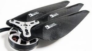
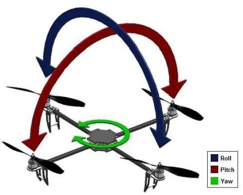
Propellers for multirotor drones such as hexacopter, octocopter and quadcopter propellers, are arranged in pairs, spinning either clockwise or anti-clockwise to create a balance. Varying the speed of these propellers allows the drone to hover, ascend, descend, or affect its yaw, pitch and roll.
Propeller speeds are varied by changing the voltage supplied to the propeller’s motor, a process that is handled by an Electronic Speed Controller (ESC). The correct signal is fed to the ESC by the drone’s flight controller, which relies on inputs from either the human pilot’s controller or autopilot and may also take into account information from an IMU (Inertial Measurement System), GPS and other sensors.
3.4 (ESC) Drone Speed Controller
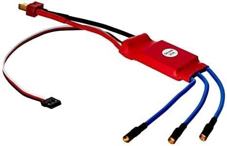
The term ESC stands for “electronic speed control is an electronic circuit used to change the speed of an electric motor, its route and also to perform as a dynamic brake. These are frequently used on radio-controlled models which are electrically powered, with the change most frequently used for brushless motors providing an electronically produced 3-phase electric power low voltage source of energy for the motor. An ESC can be a separate unit that lumps into the throttle receiver control channel or united into the receiver itself, as is the situation in most toy-grade R/C vehicles. Some R/C producers that connect exclusive hobbyist electronics in their entry-level vehicles, containers or quadcopter use involved electronics that combine the two on a sole circuit board.
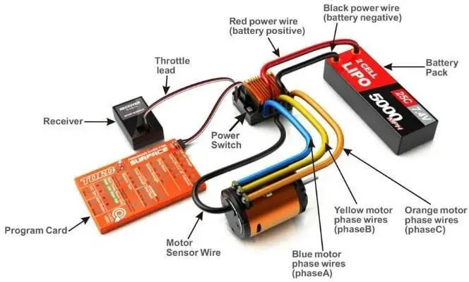
An ESC controls the speed of the motors spin of an aeroplane. It helps a similar purpose as the throttle servo of a glow powered aeroplane. It is an edge between the radio receiver of an aeroplane and the power plant. Electronic speed control will have 3- sets of wires. One wire will plug into the main battery of an aeroplane. The second wire will have a typical servo wire that plugs into the receiver’s throttle channel. And lastly, a third of the wire is used for powering the motor. The main features of an electronic speed control include a battery eliminator circuit, low voltage cut off, brake.
Brushless ESC
Brushless ESC is the modern advancement in technology once it comes to Electronic Speed Controls. It is also a bit more costly. Connected to a brushless motor, it carries more power higher performance as compared to the brushed ones. It can also last a longer period.
3.5 Lithium Polymer Battery:
A lithium polymer battery or more correctly lithium-ion polymer is a rechargeable battery of lithium-ion technology using a polymer electrolyte instead of a liquid electrolyte. High conductivity semisolid (gel) polymers form this electrolyte. These batteries provide higher specific energy than other lithium battery types and are used in applications where weight is a critical feature, such as mobile devices, radio-controlled quadcopters and some electric vehicles.
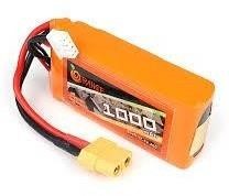
The batteries that most popular for drones are the LiPO batteries or Lithium Polymer batteries. These rechargeable batteries have taken the RC world to the next level. All the RC planes, helicopters and drones. The following are the reasons why these batteries are best for drones.
They are compact and lightweight and can be made in any shape or size depending on the type of drone it is being designed for. These batteries have high capacities i.e. they hold a large amount of energy in a small and compact package. They are pretty good at maintaining a constant power output when discharging. The rate of voltage drops when they reach a fully discharge rate is fast and can become damaging for the battery. For powering the most demanding remote-controlled quadcopters LIPO batteries have the highest discharge rates. Because they also have high charge rates, so charging in an hour is also possible. These batteries have no memory effect compared to other versions like the NiCad or the NiMh batteries.
These drones require the best battery that is lightweight and can give good charging and discharging times. Due to these factors, Lithium Polymer (Li-Po) batteries are the best choice for these drones. Using the polymer electrolyte instead of a liquid one and being rechargeable. So, choosing the right Li-Po battery we must keep the following factors in mind.
- The first thing to keep into consideration while choosing a battery is how much current drone can draw Like the current drawn from the motor also from other components.
- The second important to consider is the battery size. The perfect battery size is essential for having long and balanced flights. Let us refer the battery with the smallest size and high energy so it can serve your drone for a longer time. The physical size and weight of the battery should be compatible with your drone.
- The next thing to be kept in mind is the voltage. The batteries with high voltages have more weight too. The battery with 22 volts and other with 7 volts will have a clear difference in physical dimensions and weights also. However, we would have to make the correct decision regarding the voltage by looking at the motors and other electronic components should support the voltage of our chosen battery.
- The other important perimeter of a lithium polymer battery is the C-rating or the discharge rating. The C-rating is the performance indicator of the battery. The battery with maximum C-rating is a good choice for your drones.
- Make sure to choose the battery with the highest capacity for longer flight times.
4. Selection of Components of the Solar Power system: Solar Charge Controller, PV Module
4.1 Solar Charge Controllers
A solar charge controller manages the power going into the battery bank from the solar array. It ensures that the deep cycle batteries are not overcharged during the day and that the power doesn’t run back to the solar panels overnight and drain the batteries. Some charge controllers are available with additional capabilities, like lighting and load control, but managing the power is its primary job.
A solar charge controller is available in two different technologies, PWM and MPPT. How they perform in a system is very different from each other. An MPPT charge controller is more expensive than a PWM charge controller, and it is often worth it to pay the extra money.
4.2 Pwm Solar Charge Controller
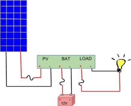
Pulse width modulation (PWM) charge controller is the most effective means to achieve constant voltage battery charging by adjusting the duty ratio of the switches (MOSFET). In the PWM charge controller, the current from the solar panel tapers according to the battery’s condition and recharging needs. When a battery voltage reaches the regulation setpoint, the PWM algorithm slowly reduces the charging current to avoid heating and gassing of the battery; yet charging continues to return the maximum amount of energy to the battery in the shortest time. The voltage of the array will be pulled down to near that of the battery. A PWM controller is not a DC to DC transformer. The PWM controller is a switch that connects the solar panel to the battery. When the switch is closed, the panel and the battery will be at nearly the same voltage.
PWM system has the following advantages:
- Higher charging efficiency
- Longer battery life
- Reduced battery over heating
- Minimizes stress on the battery
- Ability to de-sulfate a battery.
When we refer to a 12V solar panel that means a panel that is designed to work with a 12V battery. The actual voltage of a 12V solar panel, when connected to a load, is close to 18 Vmp (Volts at maximum power). This is because a higher voltage source is required to charge a battery. If the battery and solar panel both started at the same voltage, the battery would not charge.
A 12V solar panel can charge a 12V battery. A 24V solar panel or solar array (two 12V panels wired in series) is needed for a 24V battery bank, and a 48V array is needed for a 48V bank. If you try to charge a 12V battery with a 24V solar panel, you will be throwing over half of the panel’s power away. If you try to charge a 24V battery bank with a 12V solar panel, you will be throwing away 100% of the panel’s potential, and may actually drain the battery as well.
4.3 Mppt Solar Charge Controller
Nowadays, the most advanced solar charge controller available is the Maximum Power Point Tracking (MPPT). It is more sophisticated and more expensive. It has several advantages over the PWM charge controller. It is 30 to 40% more efficient at low temperatures. The MPPT is based around a synchronous buck converter circuit. It steps the higher solar panel voltage down to the charging voltage of the battery. It will adjust its input voltage to harvest the maximum power from the solar panel and then transform this power to supply the varying voltage requirement of the battery plus load. It is generally accepted that MPPT will outperform PWM in a cold temperature climate, while both controllers will show approximately the same performance in a subtropical to tropical climate. The MPPT charge controller is a DC to DC transformer that can transform power from a higher voltage to power at a lower voltage. The amount of power does not change, therefore, if the output voltage is lower than the input voltage, the output current will be higher than the input current, so that the product P=VI remains constant. Hence, to get the maximum out of a solar panel, a charge controller should be able to choose the optimum current-voltage point on the current-voltage curve: the Maximum PowerPoint. An MPPT does exactly that. The input voltage of a PWM controller is, in principle, equal to the voltage of the battery connected to its output. The solar panel, therefore, is not used at its Maximum PowerPoint, in most cases.
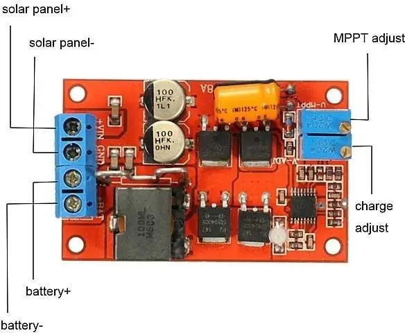
We can use a higher voltage solar array than the battery, like the 60 cell nominal 20V grid-tie solar panels that are more readily available. With a 20V solar panel, you can charge a 12V battery bank, or two in series can charge up to a 24V battery bank, and three in series can charge up to a 48V battery bank. This opens up a wide range of solar panels that can now be used for your off-grid solar system.
Temperature conditions
An MPPT controller is better suited for colder conditions. The MPPT controller can capture the excess module voltage to charge the batteries. It produces up to 20-25% more charging than a PWM controller. The PWM type is unable to capture excess voltage because the pulse width modulation technology charges at the same voltage as the battery. But when solar panels are deployed in warm or hot climates, there is no excess voltage to be transferred making the MPPT unnecessary and negating its advantage over a PWM.
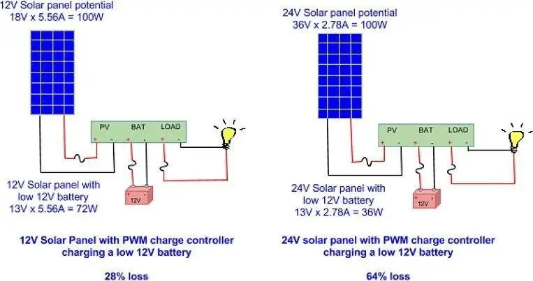
Array Voltages
PV array and battery voltages should match for PWM but PV array voltage can be higher than battery voltage for MPPT.
Battery Voltage
PWM operates at battery voltage, so it performs well in warm temperatures and when the battery is almost full while MPPT operates above the battery voltage, so it can provide a “boost” in cold temperatures and when the battery is low.
System Size
PWM is typically recommended for use in smaller systems where MPPT benefits are minimal, while MPPT is recommended for 150W-200W or higher sized systems to take advantage of its benefits.
Cost
MPPT controllers are typically more expensive than PWM controllers but are more efficient under certain conditions, so they can produce more power with the same number of solar modules than a PWM control.
4.4 Solar Panels
Solar panels are also known as photovoltaic solar modules, solar plates, solar PV modules and solar power panels etc. Solar panels are made up of a bunch of 60- 72 solar cells that convert sunlight into electricity.
Solar cells are made from an element called “silicon“. To manufacture the solar cells, fragments of silicon or silicon crystals are melted together in a mould and cut into wafers.
If we install two or more solar panels together and connect them with a solar inverter, the solar battery then becomes a solar power system that can be used in houses, companies, schools, industries etc. The solar panel is the main part of the solar system and all types of solar systems (on-grid solar systems, off-grid solar systems and hybrid solar systems) contain the same type of solar panels.
4.5 Types of Solar PV Panel
Solar panels are invented in many types and capacities. This panel varies from each other based on their formation, material used, etc. To provide a brief knowledge about all types of solar panels, we are listing their type below.
- Polycrystalline Solar Panel: Polycrystalline solar panel is most common type of solar panel. The efficiency rate of poly crystalline solar panel is around 16%-17%. These panels are best to work under extreme weather conditions. To manufacture polycrystalline solar panels, low purity silicon is used.
- Monocrystalline Solar Panel: Mono crystalline solar panels are second most successful type of solar panel. Mono Panels are made out of pure high quality silicon. The efficiency level of mono panels are more than poly panels i.e 19%-20%. These panels have blackish-hue on their surface.
- Thin Film Solar Panel: A thin-film solar panel is made up of an assembly of thin-film solar cells. These solar panels convert solar energy to electrical energy by using the principle of the photovoltaic effect. Each thin-film solar cell is made up of several layers of photon-absorbing materials. These layers can be up to 300 – 350 times smaller than the layers of standard silicon panels.
These solar panels are categorized based on the material that is used as a substrate in them. Materials such as Amorphous Silicon (a-Si), Copper Indium Gallium Selenide (CIGS), Cadmium Telluride (CdTe), and Gallium Arsenide (GaAs) are used as substrates. Out of these, thin-film solar panels with a GaAs substrate are the most efficient, about 28.8% more than others.
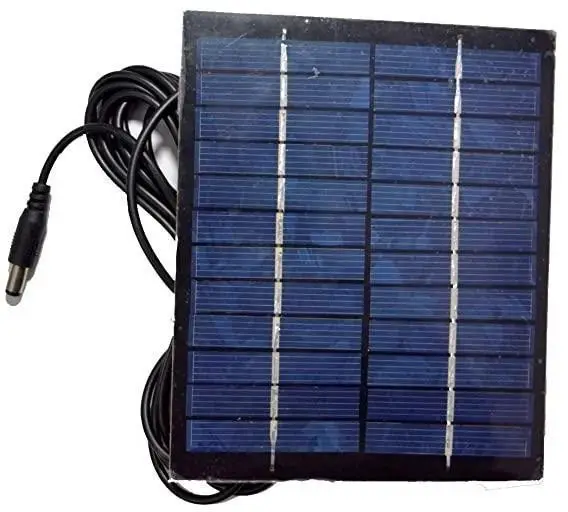
4.6 How do Thin-Film Solar Panels work?
A solar panel is basically a semiconductor device composed of a combination of various solar cells/photovoltaic cells (PV). Each PV cell is formed by a combination of p-type and n-type materials. P-type materials are those that are deficient in electrons while n-type materials are those that contain free electrons.
When sunlight falls on the panel, the electrons get excited and flow through the p-n junction thereby generating a large amount of current. This current can then be directly sent to a building to power various appliances or it can be stored in batteries to be used when required.
In the case of traditional solar panels, silicon is generally used as semiconducting material. However, in the case of thin-film solar panels, materials such as Copper Indium Gallium Selenide, Cadmium Telluride, Amorphous Silicon or Gallium Arsenide are used instead of silicon.
4.7 Size of Solar Panel
The size of a solar panel will vary from brand to brand and capacity to capacity. But for big capacity solar panels (more than 100 watts), the standard size is 1 mt. X 2 mt. and 1kW solar system contains three solar panels.
4.8 Solar Power
Power is defined as the time rate of energy usage (change in energy divided by change in time) and is measured in units of watts.
The power output from a solar panel depends on the following values:
- The Sun, or rather the power from the Sun. The power per area of the energy from the Sun at the surface of Earth is about 1000 watts per square meter.
- Orientation angle. If the sunlight is perpendicular to the solar panel, that’s best.
- The size of the solar panel. Bigger panels suck up more power.
- The efficiency of the solar panel.
Specifications:
- Monocrystalline silicon solar cells (5kw power,0.6volts,160mm thickness ).
- Maximum power point tracking(10.5A,14.2V,4s).
- Motors (650kv brushless motor,2800g thrust).
- Carbon fiber propellers (38cm length).
- Lithium polymer battery (4s,35c,14.4 volts).
- Electronic speed controller (30 amp,upto 16volts,2-4s).
4.9 System Block Diagram:
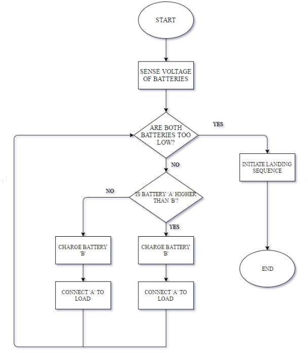
5. Thrust Test
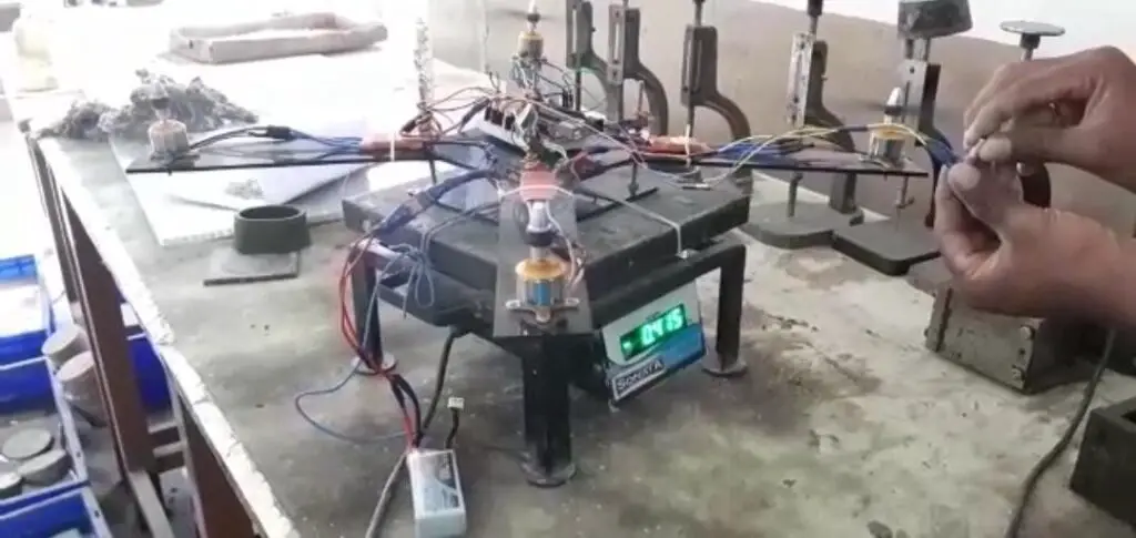
5.1 Practical Thrust Calculations:
- Initial drone weight=1040g
After resetting the simple balance the readings are:
- potentiometer-corresponding lift.
- start-70g.
- quarter-140g.
- half-240g
- more than half-355.
- three fourth-430(consant).
- maximum thrust-540g.
since gravity is constant and hence neglected.
5.2 Circuit Diagram
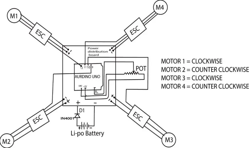
5.3 Aerodynamics of the Solar Powered Quadcopter:
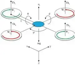
FT=CtρD4ω2
Q=CPD5ω2 / 2п
Where,
- Ft : Thrust force.
- Q : Drag torque.
- Ct : Thrust coefficient.
- Cp : Power coefficient.
- ρ : Density of air.
- D : Propeller diameter.
- ω : Rotation speed of the propeller.
5.4 Theoretical Model of Solar Powered Quadcopter

- Fi = Kf * ꙍi2
- Mi = Km*ꙍi2
- My = (F1-F2)* L
- Mx = (F3-F4)*L
- Weight = mg
Newton’s second law of motion
For the linear motion: Force =mass * linear acceleration
For rotational motion Torque = Inertia * angular acceleration
Hover Condition
Condition for hovering
- mg = F1+F2+F3+F4
- All moments = 0
Equations of motion
- mr = F1+F2+F3+F4-mg
- mr = 0
Rise Motion
Condition for hovering
- mg < F1+F2+F3+F4
- All moments = 0
Equations of motion
- mr = F1+F2+F3+F4-mg
- mr > 0
Yaw Motion
Condition for hovering
- mg = F1+F2+F3+F4
- All moments ≠ 0
Equations of motion
- mr = F1+F2+F3+F4-mg
- IzzΨ = M1+M2+M3+M4
Pitch and Roll Motion
Condition for hovering
- mg < F1+F2+F3+F4
- All moments ≠ 0
Equations of motion
- mr = F1+F2+F3+F4-mg
- IxxØ = (F3-F4) * L
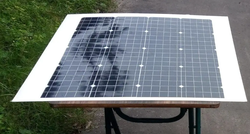
5.6 Design Of Solar Powered System Using Autocad
6. Conclusion
A lightweight solar-powered flying quadcopter is being developed for environmental monitoring purposes. Which increases the consumption of renewable energy and can reduce the usage of batteries. The structural construction of the flying model has accomplished in such a way that the solar panel gets the best position to gain optimum solar energy together with an additional crash protection frame structure. The designed circuitry of the solar charge controller and boost converter focuses on the lightweight aspect to make flying possible with added weight for various environmental sensors mounted for constant monitoring purposes.
References
- K. S. Rahman, Md. Rokonuzzaman, G. B. Xue, R. I. Thakur, K. M. Kabir, M. A. Matin, S. K. Tiong, N. Amin , Published by International Journal of Engineering and Advanced Technology (IJEAT) (A Light Weight Solar Powered Mini quadcopter
- P.CASTILLO, P.GARCIA, R.LOZANO, P.ALBERTO; Dumlupinar university, Drone Design
- Prof. Ching-Fuh Lin’s group at National Taiwan University Solar-Powered Quadcopter Developed in Taiwan
- GREPOW.B, Lipo Battery For Drone, Lipo Battery for Drone: Introduction, Choice And Safety:
Credit: This project “The Design of Solar Powered Quadcopter” is completed by Kare Snehita, Kolakaluri Daisy, Kovela Bargav Sai Krishna, Odugu Bhavani Sankar, and Vishnubhatla Sai Bharadwaj from the Department Of Mechanical Engineering, Velagapudi Ramakrishna Siddhartha Engineering College (Autonomous) Kanuru, Vijayawada. Andhrapradesh-520007, INDIA.

very good project .
can you provide the report of this project for study purpose
Hi
Can i get the report & presentation on Design of Solar rechargeable quadcopter?