A final year project on “Construction of A Low-Cost Smoke Detector” submitted by Suleiman Abdulhameed Bashir (from FEDERAL UNIVERSITY GUSAU) to extrudesign.com.
INTRODUCTION
1.0 Introduction
A smoke detecting device is a device that detector senses smoke as an indicator of fire nearby or non-smoking area. Smoke detectors are designed to provide early warning for fire, involving ordinary combustible materials, that is expected to progress through distinct incipient and/or smouldering stages. The type, volume, and density of smoke produced during the fire development process will vary greatly depending on the fuels involved and the amount of oxygen available. Typically, the greatest volume of visible smoke is produced during the ignition (incipient) stage and the smouldering stage.
1.1 Background of Study
A smoke detector is a device that detects the presence of fire. Commercially security devices issue signal to a fire alarm control panel as part of a fire alarm system, while household smoke detectors generally issue a local audible or visual alarm from the detector itself. Smoke detectors are housed in a plastic enclosure, typically shaped like a disc about 150 millimetres (1 in) thick, but shape and size vary (culled from nfpa.org 2015).
The first automatic electric fire alarm was patented in 1890 by Francis Robbins Upton (culled from Francis Robbins Upton) an associate of Thomas Edison (culled from New York Times 2011). George Andrew Darby patented the first European electrical heat detector in 1902 in Birmingham, England (culled from an Electric Heat Indicator and Fire-alarm) (culled from Prosser, Richard. 1970). There are two types of smoke detectors invented which are ionization chamber smoke detector and photoelectric smoke detector. In 1939 Swiss physicist Ernst Meili devised an ionization chamber device capable of detecting combustible gases in mines (culled from How smoke detector is made). He also invented a cold cathode tube that could amplify the small signal generated by the detection mechanism to a strength sufficient to activate an alarm (culled from How smoke detector is made) while the photoelectric (optical) smoke detector was invented by Donal Steele and Robert Emmark of Electro Signal Lab and patented in 1972 (culled from Optical Smoke Detector).
As of now there, are different types of detectors invented with different method of detection such fire detection using camera captured area, GSM embedded fire detector which sends an SMS to the appropriate personnel, a wireless fire detecting sensor network using ARM 7 base microcontroller and so on.
But the current rate of poverty, there is a need to or invent a smoke detecting device that is low cost and will have to perform the work of any other smoke detector and to an extent of sounding alarm so as to give early awareness of the presence of fire. This is to be done so as to safeguard possibly each house. To avoid the destruction of life and properties and to make sure that every house has a right to a smoke detector.
Smoke detectors are not the same as ‘smoke alarms’. A smoke alarm includes the
audible sounder in the same unit as the smoke sensor, while a smoke detector contains only the sensor and relies on external sounders (culled from NFPA 72, 2013). Smoke detectors are often used in large buildings, whereas smoke alarms are usually found in private residences. Smoke detectors are often part of a fire alarm system that may include sprinklers, fire alarm pull stations, and a control panel. (Frank Quackenbush, 2015).
Smoke detectors work mainly on two principles: Optical and Ionization. In optical smoke detectors, LED acts as a light source and at a distance from LED we have a photo detector. In absence of smoke, light reaches the detector without any decrease in intensity. When smoke enters the room, some light is scattered by smoke particles and hence light intensity reaching the detector is less and thus the alarm is triggered. The optical smoke detector has a very high response time. Ionization smoke detector uses radioactive isotope americium-241 to detect smoke. But Ionization smoke detector is rejected as it is more prone to the false alarm. All these are not reliable tool to detect fire and smoke. Even when the fire is detected, it is detected in a very late stage where any precautionary measures will prove futile (culled from IJSRP 2014).
Fire alarm system provides an early warning of fire so that people can be evacuated and immediate action can be taken to stop or eliminate the fire effect as soon as possible so that properties and lives will not be at stake (culled from IJCTT 2018), (Elbehiery, H. 2012). This is to enable or ensure human safety and his properties against fire in both houses and industrial settings, in this era different type of smoke or fire detecting device has been developed as earlier stated before. This device varies base on the method of detection. This device is derived from two basic smoke detectors, namely:
- The photoelectric smoke detector (PSD).
- The ionization chamber smoke detector (ICSD).
1.1.1 Photoelectric Smoke Detector
Photoelectric technology uses a beam of light and a photocell inside the chamber, so when smoke enters the chamber it deflects the beam, causing it to strike the photocell and showing there is a smoke emergency in the occupancy (culled from Fleming 2011). This type of smoke detector reacts most quickly to smouldering fires that release relatively large amounts of smoke.
1.1.2 Ionization Chamber Smoke Detector
Ionization smoke alarms use small amounts of radioactivity that consists of two plates with a voltage across them, in this process the negative electron is attracted to the plate with a positive voltage, and the positive atom is attracted to the plate with a negative voltage current that flow all the time between the two ionization smoke alarms use small electrodes in the chamber.
So, when smoke enters the ionization chamber, it disrupts this current and the smoke particles attach to the ions and neutralize them. The smoke alarm senses the drop-in current between the plates, which cause the alarm to activate (culled from Fleming 2011). The ionization chamber smoke detector is quicker at sensing flaming fires that produce little smoke.
1.2 Statement of the Problem
A smoke detector is a device that detects the smoke and it is known that smoke comes before the fire and there is no fire without smoke. Therefore, there is a need for smoke detectors at a low or cheap rate which will reduce the rate of fire destruction if not annihilate which will be affordable by most households.
1.3 Justification of the Study
This project would ensure that cheap materials would be implemented into cheap and efficient smoke detectors which would be affordable to most people. This work would give the people in the rural and urban areas access to smoke detection.
1.4 Aim and Objectives
The aim of this project is to be able to construct an efficient, reliable and low-cost smoke detector.
The objectives of this project are to:
- To provide early warning signal in the event of fire.
- To give each household an access to a detector.
- To alert the occupants of such building of the impending danger.
- To enables emergency action to be taken to prevent fire outbreak.
- Lives and property will be preserved if immediate action is carried out.
1.5 Scope and Limitation
This is to construct a device that detect the presence of smoke or heat in the environment where it’s been mounted so as to avoid further fire disaster, and this can be used to create awareness to the people in the area and also should be affordable.
LITERATURE REVIEW
2.0 Introduction
A smoke detecting device is a device that detector senses smoke as an indicator of fire nearby or non-smoking area. Smoke detectors are to provide early warning for fire, involving ordinary combustible materials, that is expected to progress through distinct incipient and/or smouldering stages.
S. George, et al (IJSRP 2014), present a system that can efficiently detect fire after the image of the area has been captured by a camera. They propose a method that first detects smoke and then the potential fire region. If it keeps on varying, then it is confirmed as a fire region and an alarm is sounded. The CCTV camera used here will capture the frame and will provide the computer for the processing which will be based on MATLAB. The processing will comprise the detection of smoke and fire. Detecting smoke and then fire reduces the false alarm rate to a great extent. The application of Image processing in fire detection will make use of the high brightness and colour characteristic of fire flame. The recently captured frame will be compared with the reference frame to obtain a value and is compared with the threshold value and results are produced. The use of this mentioned technique will also help to detect even the small fire, whereas the conventional techniques fail at these places. The proposed methods used were fire detection, smoke detection, colour space detection and flow chart. And in the working they made use of RGB Band Separation, Brightness and Saturation Calculation, Smoke Detection, Detection of Potential Fire Region, Extracting Fire Flames and Fire Region Confirmation, getting the results in which when smoke is detected it displays “Smoke is detected” and if not, the process continues.
Izang, A. A., et al (2018) built a system with a GSM module embedded in it, which helps to send SMS to the homeowner and the fire service personnel when there is a fire outbreak before it goes out of control. In their research, special attention was put on the critical condition that makes the component and the module operate efficiently. All components are discussed and the functions. The major problem accosted in engineering is to fully and correctly specify the requirements of the. The “Fire Alarm System using SMS” system process involves a full analysis of the system specification and hardware. For the hardware, they used components like Environmental sensors S1 to S4, Microcontroller and GSM module.
Suneel M. et al, (2011), in their paper, the wireless sensor network is realized using an ARM 7 based microcontroller. The LPC2148 is a very popular ARM7 microcontroller with 512 KB flash, 64 KB of RAM and with several I/O peripherals. When the potential fire is detected, the smoke sensor sounds an alarm. It also transmits a signal wirelessly to other sensors in the network. The microcontroller forms the main unit of the system. It receives input from the sensors and wirelessly sends information to other sensors in the network to sound an alarm thereby preventing any disaster from occurring. GNU ARM/Keil compiler will be used for building the applications. The LPC2148 development board will be used to test the built application. Additional sensors and wireless nodes will be used to demonstrate the complete setup. These components were used to build a real-time security control system for smoke and fire detection using ZigBee. The hardware used was classified into four which comprises of Input Device, Output device, Control panel and Power supply.
Kausik Sen, et al, (2015), in their paper basically a low-cost fire detection and control system based on smoke and heat detection was proposed. Their device comprised of a combination of electrical/electronic devices/equipment’s working together to detect the presence of fire and alert people through an audio or visual medium after detection. These alarms may be activated from smoke detectors or heat detectors which, when detects fire. Then, it automatically operates a relay which can be used to send Short Message Service (SMS) to the registered mobile numbers and switch on a water sprayer or a Solenoid Pump to spray water or fire ceasing foam. In the method used were eight (8) main unit in the system which consists of Sensor, ID sender unit, Data line, Memory unit, Display unit, SMS (Short Message Service) sender, Pump starter unit and Power supply. They performed the experiment in their laboratory and noticed its feasibility. It is also seen that the system does not respond if the fire generates very small smoke particles and a very small amount of heat. The system does not display properly if two or more than two rooms or blocks are affected at the same time.
Kelebaone Tsamaase1, et al (2017), designed a portable fire detector that can easily detect the sudden rate of change of temperature and sound an alarm if the pre-set value were exceeded. The detector is said to be portable because it can be moved from one place to another. The system incorporates a thermistor and the Arduino IDE which can be programmed using various languages such as C++. The circuit was designed and simulated, with simulation results showing that the system is able to fulfil its objectives. A prototype was built and demonstrated that the system is able to respond to the rate of change of temperature. In their experiment, they made use of Arduino UNO board, Breadboard, Thermistor, LED and a Buzzer, Two resistors and a 9V battery. The programmed code assumes that a temperature change (rise) of 50C, should not occur in less than a minute. In the case where this happens then, the model is programmed to immediately sound an alarm, thereby notifying occupants in a building of fire danger. And lastly, they were able to get the outcome to be as expected.
Manav Jain and Mohammad Jawaid Siddiqui (2014), in their research, specify various circuits for detecting fire or smoke. Among the circuits observed were Thermistor based circuit, Low-cost fire alarm circuit, Low power circuit, and Smoke detectors. In their conclusion of the research, they discovered that electronic circuits can be designed for fire-based alarms and they provide very high efficiency and can be used for security reasons. And that the various circuits discussed can be used.
Brawner Brian L., et al (2017), the initial stage included preliminary development of pre-made devices, coding, and testing on-site. The testing was conducted in the University of Science and Technology of Southern Philippines (USTP)-Science complex in March 2017 with pre-selected dates. The material and method used were the MQ2 gas sensor which detects carbon monoxide, smoke and other gas, Power source, DC power supply, Arduino microcontroller, Computer and Air quality variable interpretation. The results of their study show that low cost developed microcontroller (Arduino Uno)-MQ2 gas sensor was functioning within the specifications of the sensor’s sensitivity and the however needs improvement and calibration for convenient application sampling on the study site.
Neelam Kumari, et al (2018), these group people designed a smoke detector using a microcontroller this was to assess the uncertainty associated with these estimation methods. Experimental data was used to evaluate recommended alarm thresholds and to quantify the associated error. In there, the microcontroller-based system monitors the condition of the system and on receiving the fault the controller activates a buzzer for information and monitor it in a LED. The components used there were transformer (0-12) vac, 1Amp, IC 7805 & 7812, diodes IN 4007, LED and resistors. Here 230V, 50 Hz ac signal is given as input to the primary of the transformer and the secondary of the transformer is given to the bridge rectification diode. The O/P of the diode is given as I/P to the IC regulator (7805 &7812) through a capacitor (1000mf/35v). The O/P of the IC regulator is given to the LED through resistors. And the result of the project was found to be working satisfactorily. The response time for any fault in this is approximately 1 sec. The system tolerance is well below the limits of experimental errors.
Punam P. and Shamik T. (2012), in their project they used an automatic fire detection system that use physical sensors to detect and respond to a fire. Also, the physical sensor uses the chemical properties in the air are acquired by the sensor and use by a fire detection system to raise an alarm. They used a different model for fire detection such as RGB colour model, YCbCr colour model, motion detection in video and Area detection which eventually yield their result which is sample RGB image frames having a fire, which contains sub-images of different steps in the algorithm: 1st image frame, 2nd image frame having flame, the red component of fire pixel according to condition, a motion was detected between these two frames, and the last sub-image showed the fire pixel detected in the image.
Shin Juh Chen et al (2007), in their project they found out that fire detection systems located in aircraft cargo compartments are currently based only on smoke detectors. They generate about 200 false alarms per year for U.S. registered aircraft. The number of false alarms was growing as more planes are outfitted with smoke detectors and air travel expands, the experimental method used was a fire alarm algorithm to test the fire alarm algorithm and compare its performance with a commercial aircraft smoke detector was obtained at the University of Maryland. And at the end, a total of 30 fires, either smouldering or flaming, was generated to test the fire alarm algorithm described above. Combustible materials included samples of HDPE beads, PVC clad wire, mixed plastics, mixed fabric, and green canvas. Liquid fuels included methanol, heptane and toluene. The samples were ignited using different methods depending on the type of material. Liquid fuels were ignited using a lighter. Tables were used to analyse the data gotten, table 1 shows the list of the material tested, the ignition method employed and the type of fire generated.
Prerna B. Pagar and Popat R. Thorat (2016), their paper gives an implementation & performance evaluation of real-time based indoor fire and smoke detection without sensor by video processing technique. And the system being implemented contains the following parts: fire detection, smoke detection, data fusion, control module. The system proposes an algorithm for RGB and YCbCr colour space for fire detection with a classification of pixels and Gaussian mixture model (GMM) in HSV colour space for smoke detection. In addition, separation of smoke and fire pixels was done using colour information (within appropriate spaces, specifically chosen in order to enhance specific chromatic features) were performed. For the output, the method uses cell phone messages for the control action. The system was implemented in MATLAB version 7.10.0.499(R2010a).
Toufiqul Islam, Syed Asif Abdullah, and Golam Sarowar (2013), their paper describes the design and engineering of a wireless control system for smoke and fire detection with alarming provision, SMS sending and fire extinguishing by a vehicle. For the design of this system, they made use of the following components: Transmitter, Receiver, Tone Generator, PIC microcontroller, Temperature sensor, Low Battery Sensor and Smoke sensor. The device was constructed and smoke/fire detection technology save the lives of people and property more and more. The SMS sending feature makes the system more reliable and more sophisticated in terms of life safety as it is done with the help of a GSM module.
2.1 Ionization Smoke Detector
Ionization smoke detector uses a radioisotope, typically americium-241, to ionize air; a difference due to smoke is detected and an alarm is generated. Ionization detectors are more sensitive to the flaming stage of fires than optical detectors, while optical detectors are more sensitive to fires in the early smouldering stage (culled from Fleming, Jay 2016). The smoke detector has two ionization chambers, one open to the air, and a reference chamber that does not allow the entry of particles. The radioactive source emits alpha particles into both chambers, which ionizes some air molecules. There is a potential difference (voltage) between pairs of electrodes in the chambers; the electrical charge on the ions allows an electric current to flow.
Ionization smoke detectors monitor ions or electrically charged particles in the air. If smoke enters the device, an electrical imbalance is created. When combustion particles enter the detector, they obstruct the flow of the current, setting off an alarm when the current gets too low.
Ionization smoke detectors respond well to fast flaming fires and are best suited for areas containing highly combustible material such as cooking fat, paint, or flammable liquids. They are inexpensive and are the most popular type of smoke detector in the United States.
Ionization detectors are usually quicker to react than photoelectric detectors, but they are sometimes unable to differentiate between smoke and steam, making them prone to false alarms.
2.2 Photoelectric or Optical Smoke Detector
A photoelectric or optical smoke detector contains a source of infrared, visible, or ultraviolet light (typically an incandescent light bulb or light-emitting diode), a lens, and a photoelectric receiver (typically a photodiode). In spot-type detectors, all of these components are arranged inside a chamber where air, which may contain smoke from a nearby fire, flows. In large open areas such as atria and auditoriums, optical beam or projected-beam smoke detectors are used instead of a chamber within the unit: a wall-mounted unit emits a beam of infrared or ultraviolet light which is either received and processed by a separate device or reflected back to the receiver by a reflector. In some types, particularly optical beam types, the light emitted by the light source passes through the air being tested and reaches the photosensor. The received light intensity will be reduced due to scattering from particulates of smoke, air-borne dust, or other substances; the circuitry detects the light intensity and generates the alarm if it is below a specified threshold, potentially due to smoke (culled from Brazzell, D. 2012). In other types, typically chamber types, the light is not directed at the sensor, which is not illuminated in the absence of particles. If the air in the chamber contains particles (smoke or dust), the light is scattered and some of it reaches the sensor, triggering the alarm (culled from Brazzell, D. 2012).
2.3 Carbon monoxide and carbon dioxide detection
Carbon monoxide sensors detect potentially fatal concentrations of carbon monoxide gas, which may build-up due to faulty ventilation where there are combustion appliances such as gas heaters and cookers, although there is no uncontrolled fire outside the appliance (culled from New York City Fire Department 2012).
High levels of carbon dioxide (CO2) may indicate fire and can be detected by a carbon dioxide sensor. Such sensors are often used to measure levels of CO2 which may be undesirable but not indicative of a fire; this type of sensor can also be used to detect and warn of the much higher levels generated by a fire. One manufacturer says that detectors based on CO2 levels are the fastest fire indicators, and also, unlike ionization and optical detectors, detect fires that do not generate smoke, such as those fuelled by alcohol or gasoline. CO2 fire detectors are not susceptible to false alarms due to particles, making them particularly suitable for use in dusty and dirty environments (culled from Carbon Dioxide – Life and Death 2018).
2.4 Video Smoke Detector
Video smoke detection (VSD) is based on the computer analysis of video images provided by CCTV cameras, automatically identifying the particular motion patterns of smoke and alerting the system operator to its presence in the shortest possible time. VSD systems have been installed in places such as turbine halls, historic buildings, road tunnels, rail depots, warehouses, shopping malls, and aircraft hangars. Some of them only detect smoke, although others can also detect a flame, as well as providing motion detection and other surveillance/security features.
2.5 Some Materials Used in the Reviewed Literature
2.5.1 MQ2 Smoke Sensor
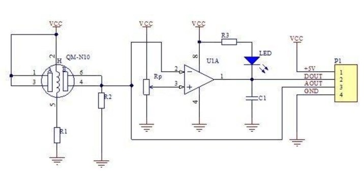
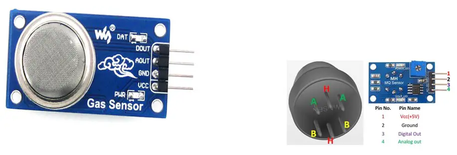
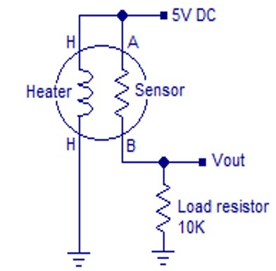
MQ2 Smoke Sensor is a device used to detect the presence of LPG, Propane and Hydrogen, also could be used to detect Methane and other combustible steam, it is low cost and suitable for different application. The sensor is sensitive to flammable gas and smoke. The smoke sensor is given 5 volts to power it. The smoke sensor indicates smoke by the voltage that it outputs. The more the smoke more the output. The sensor’s conductivity is higher along with the gas concentration rising. Please use a simple electro circuit, convert the change of conductivity to correspond output signal of gas concentration. The MQ2 has an electrochemical sensor, which changes its resistance to different concentrations of varied gasses. The resistance across the pin depends on the smoke in the air in the sensor. The resistance will be lowered if the content is more. And voltage is increased between the sensor and load resistor. MQ2 Circuit in appendix 1.
Specification of MQ2 Sensor
- Power supply: 4.5V to 5V DC.
- High sensitivity to Smoke, Propane, LPG and Butane.
- Wide range high sensitivity to combustible gases.
- Long life and low cost.
- Analog and Digital output.
- Onboard visual LED indicator.
- Sensor type: Semiconductor.
- Simple drive circuit.
- Concentration: 300-10000ppm (Combustible gas).
- Compact design and easily mountable.
2.5.2 LM358 Integrated Circuit
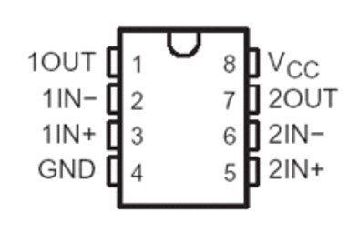
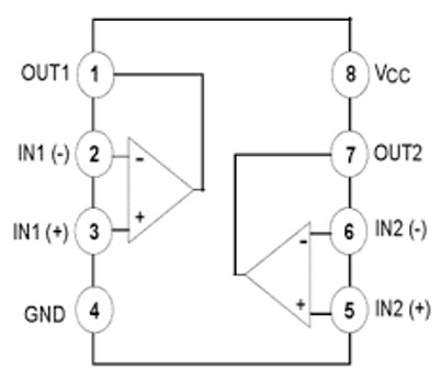
The LM358 is a low power dual operational amplifier integrated circuit originally introduced by National Semiconductor. It is used in detector circuits. The abbreviation LM358 indicates an 8-pin integrated circuit, comprising two operational amplifiers at low power. The LM358 is designed for general use as amplifiers, high-pass filters, low bandpass filters, and analogue adders, as shown in appendix 2.
2.5.3 Vero Board
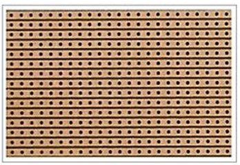
Veroboard is a brand of stripboard, a pre-formed circuit board material of copper strips on an insulating bonded paper board which was originated and developed in the early 1960s by the Electronics Department of Vero Precision Engineering Ltd (VPE). It was introduced as a general-purpose material for use in constructing electronic circuits – differing from purpose-designed printed circuit boards (PCBs) in that a variety of electronic circuits may be constructed using a standard wiring board.
The first single-size Veroboard product was the forerunner of the numerous types of prototype wiring board which, with worldwide use over five decades, have become known as stripboard. As with other stripboards, in using Veroboard, components are suitably positioned and soldered to the conductors to form the required circuit. Breaks can be made in the tracks, usually around holes, to divide the strips into multiple electrical nodes enabling increased circuit complexity.

This type of wiring board may be used for initial electronic circuit development, to construct prototypes for bench testing or in the production of complete electronic units in small quantity.
Veroboard was first used for prototype construction within Vero Electronics Department in 1961. The images of a binary decade counter sub-unit clearly show both the assembled components and the copper conductors with the required discontinuities.
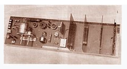
A number of these sub-units were interconnected through connectors mounted on a motherboard similar to that shown in the Veroboard Display image and comprised a very early PCB-based backplane system. Each sub-unit had a digital capacity equivalent to 1/2 byte of data storage – i.e. 2,000,000 would be required to store 1 megabyte.
Two forms of Veroboard are produced with a hole pitch of 2.54 mm (0.1 in) or 3.5 mm (0.15 in). The larger pitch is and was considered easier to assemble, especially at a time when many constructors were still more familiar with valves and tag strips.
The increasingly popular integrated circuits in dual in-line packages would only fit the 0.1 boards. Very soon 0.1 pitch became by far the dominant form. Integrated circuits and the common layout of short parallel strips protruding from the sides of an IC package encouraged the development of specialist boards such as Verostrip. This was a long, thin board with the copper strips arranged transversely, rather than the usual lengthwise. A ready-cut central gap was provided to isolate the sides of the IC.
2.5.4 Buzzer
Buzzer is a device that is used to create awareness to people the means of sound wave, this device always creates a blipping and it is used usually in the alarm system.
2.6.5 Light Emitting Diode (LED)
The light-emitting diode is mainly a P-N injected semiconductor device, adopting direct band-gap semiconductor materials to generate light through electron hole-pair recombination. The energy of the emitted photons is approximately equal to the energy difference of the energy bandgap (culled from Sze, 1985; Bhattacharya, 2002; Schubert, 2010). Virtually all LED structures employ double heterostructures. They consist of two confinement layers and an active region (culled from Schubert, 2010).
2.5.6 Resistor
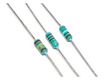
Is a passive two-terminal electrical component that implements electrical resistance as a circuit element. In electronic circuits, resistors are used to reduce current flow, adjust signal levels, divide voltages, bias active elements, and terminate transmission lines, among other uses. High-power resistors that can dissipate many watts of electrical power as heat, may be used as part of motor controls. in power distribution systems, or as test loads for generators. Fixed resistors have resistances that only change slightly with temperature, time or operating voltage. Variable resistors can be used to adjust circuit elements (such as volume control or a lamp dimmer), or as sensing devices for heat, light, humidity, force, or chemical activity.
Resistors are common elements of electrical networks and electronic circuits and are ubiquitous in electronic equipment. Practical resistors as discrete components can be composed of various compounds and forms. Resistors are also implemented within integrated circuits.
The electrical function of a resistor is specified by its resistance: common commercial resistors are manufactured over a range of more than nine orders of magnitude. The nominal value of the resistance falls within the manufacturing tolerance, indicated on the component.
One common scheme is the RKM code following IEC 60062. It avoids using a decimal separator and replaces the decimal separator with a letter loosely associated with SI prefixes corresponding with the part’s resistance. For example, 8K2 as part marking code, in a circuit diagram or in a bill of materials (BOM) indicates a resistor value of 8.2 kΩ. Additional zeros imply a tighter tolerance, for example, 15M0 for three significant digits. When the value can be expressed without the need for a prefix (that is, multiplicator 1), an “R” is used instead of the decimal separator. For example, 1R2 indicates 1.2 Ω, and 18R indicates 18 Ω.
2.5.7 Capacitor
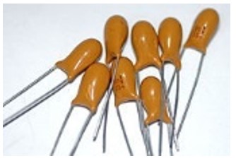
A capacitor is a passive two-terminal electronic component that stores electrical energy in an electric field. The effect of a capacitor is known as capacitance. While some capacitance exists between any two electrical conductors in proximity in a circuit, a capacitor is a component designed to add capacitance to a circuit. The capacitor was originally known as a condenser or condensation. The original name is still widely used in many languages, but not commonly in English.
The physical form and construction of practical capacitors vary widely and many capacitor types are in common use. Most capacitors contain at least two electrical conductors often in the form of metallic plates or surfaces separated by a dielectric medium. A conductor may be a foil, thin film, sintered bead of metal, or an electrolyte. The nonconducting dielectric acts to increase the capacitor’s charge capacity. Materials commonly used as dielectrics include glass, ceramic, plastic film, paper, mica, air, and oxide layers. Capacitors are widely used as parts of electrical circuits in many common electrical devices. Unlike a resistor, an ideal capacitor does not dissipate energy.
Capacitance is defined as the ratio of the electric charge on each conductor to the potential difference between them. The unit of capacitance in the International System of Units (SI) is the farad (F), defined as one coulomb per volt (1 C/V). Capacitance values of typical capacitors for use in general electronics range from about 1 picofarad (pF) (10−12 F) to about 1 millifarad (mF) (10−3 F).
The capacitance of a capacitor is proportional to the surface area of the plates (conductors) and inversely related to the gap between them. In practice, the dielectric between the plates passes a small amount of leakage current. It has an electric field strength limit, known as the breakdown voltage. The conductors and leads introduce an undesired inductance and resistance.
Capacitors are widely used in electronic circuits for blocking direct current while allowing alternating current to pass. In Analog Filter networks, they smooth the output of power supplies. In resonant circuits, they tune radios to particular frequencies. In electric power transmission systems, they stabilize voltage and power flow (culled from Bird, John 2010). The property of energy storage in capacitors was exploited as dynamic memory in early digital computers (culled from Floyd, Thomas 2005).
2.5.8 Potentiometer
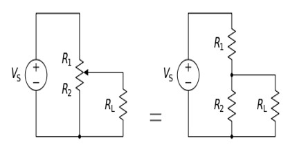
A potentiometer is a three-terminal resistor with a sliding or rotating contact that forms an adjustable voltage divider (culled from IEEE 2000). If only two terminals are used, one end and the wiper, it acts as a variable resistor or rheostat. The measuring instrument called a potentiometer is essentially a voltage divider used for measuring electric potential (voltage); the component is an implementation of the same principle, hence its name.
Potentiometers are commonly used to control electrical devices such as volume controls on audio equipment. Potentiometers operated by a mechanism can be used as position transducers, for example, in a joystick. Potentiometers are rarely used to directly control significant power (more than a watt) since the power dissipated in the potentiometer would be comparable to the power in the controlled load.
There are a number of terms in the electronics industry used to describe certain types of potentiometers:
- slide pot or slider pot: a potentiometer that is adjusted by sliding the wiper left or right (or up and down, depending on the installation), usually with a finger or thumb
- thumb pot or thumbwheel pot: a small rotating potentiometer meant to be adjusted infrequently by means of a small thumbwheel
- Trim pot or trimmer pot: a trimmer potentiometer typically meant to be adjusted once or infrequently for “fine-tuning” an electrical signal

2.5.9 Bread Board
This is used in the construction of a prototype circuit which will later be transferred to a Vero Board.
MATERIALS AND METHOD
3.0 Introduction
This section discusses the construction of the device using ionization method. The materials that make up the entire system is discussed in this chapter. The principle of operating the device is also discussed.
3.1 Materials
The materials needed for this project are MQ2 Smoke sensor, LM358 chip, Vero board, 9V DC Battery, jumper wire, buzzers, LED (Red and Green), Resistors (10kΩ x 2, 330Ω ), Capacitor (0.1µF), Potentiometer and Bread board.
3.2 Method
As depicted in the figure: 1.7. A Smoke detector (using ionization method) would require both series and parallel connections, in which the smoke detector would be connected to two LEDs (Red and Green) and a microcontroller at the same time, and one of the LEDs (Green) for an indication that the device is working perfectly and the other (Red) is for the detection of smoke. The microcontroller will serve as the monitor for the sensor and lastly a DC battery would serve as a power source for the device.
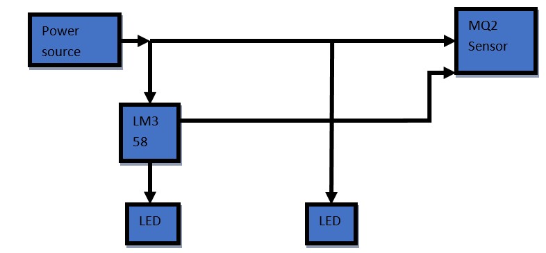
3.2.1 MQ2 Smoke Sensor
MQ2 Smoke Sensor is a device used to detect the presence of LPG, Hydrogen, and also could be used to detect Methane and other combustible steam, it is low cost and suitable for different application. Sensor is sensitive to flammable gas and smoke. In the project, it is used as the sensory device.
3.2.2 LM358
The LM358 is a low power dual operational amplifier integrated circuit originally introduced by National Semiconductor. It is used in detector circuits, it serves as the processor of the device.
3.2.3 LED (Light Emitting Diode)
Light emitting diode is mainly a P-N injected semiconductor device, adopting direct band-gap semiconductor materials to generate light through electron hole-pair recombination. This is used as an indicator and also flashlight in some cases. As of this project they are used as indicator of smoke.
3.2.4 Power Source
A power source is a means of generating power supply which could be in two form AC (Alternating Current) or DC (Direct Current), which in this case we use DC power supply.
3.3 Circuit of the Smoke Detector
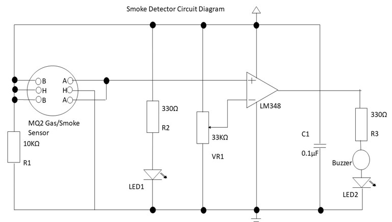
The circuit diagram in Figure: 2.0. Consists of two sections namely the input and the output sections, this section serves different purpose on the device.
The prototype of the device would be done on a bread board, it will contain the materials listed above. The LM358 IC would be mounted first, the first terminal would be connected to the potentiometer’s (shown in appendix 3) third terminal as well as the capacitor’s positive terminal and the negative terminal of the capacitor would be connected to the 8th terminal of the IC (LM358). The 4th terminal of the IC would be connected to a resistor which is connected to the red LED, the negative terminal of the red LED is connected to the green LED negative terminal. The potentiometer is connected to the green LED and the MQ2 smoke sensor which is connected to the red LED and the IC (LM358), the IC is connected to the power source whereas the potentiometer would be the control for the sensitivity of the smoke sensor (MQ2), and LM358 IC is the microprocessor or a programmed computer of the device, while the resistors and the capacitor are to serve as voltage divider and a means of storing energy for the device respectively, the LED’s and the buzzer serves as the indicators and lastly the DC battery of 9V as the power source. After all the process it will be moved to a Vero Board for permanent assembling of the components.
The input circuit depicted in Figure: 1.8. consists of the MQ2 smoke sensor and a resistor, the smoke sensor receives the amount of smoke needed to trigger the alarm and then the resistor serves as voltage divider for the smoke sensor so as to allow the passage of the appropriate voltage needed to run the sensor.
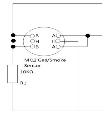
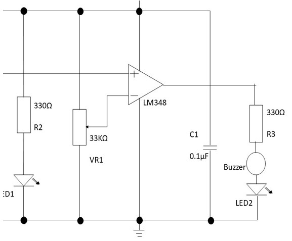
Figure: 1.9. depict the output section which consists of two resistors and a capacitor, two LEDs are also present and a buzzer, when smoke is being detected, the first LED (Red) indicates that the device is active while the second LED (Green) indicate the presence of smoke which would issue an alarm mode and also the buzzer will be triggered to sound an alarm.
RESULT AND DISCUSSION
4.0 Result
The aim of this project is to construct a low-cost smoke detector which is achieved. The device constructed is able to detect the presence of smoke from the range of 11.5 feet breath and 14 feet length; it is efficient, reliable and most importantly low cost. The audio and visual alarms were triggered accordingly at closest range. From the observations, the system can achieve the functionality of a smoke detector device, in the sense that it can efficiently and comfortably prevent fire outbreak.
4.1 Discussion
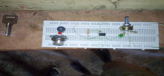
Figure 2.1 shows the final circuit after assembling on breadboard, but with the power supply switched off. As expected, all the LEDs, and the buzzer were off regardless of the environmental smoke conditions.
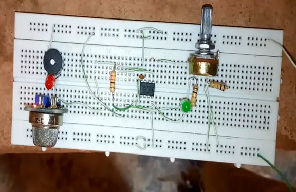
Figure 2.2 was taken while the circuit was being tested while mounted on a breadboard. The buzzer and LEDs were off, while the green LED was on, as expected. Which is an indicator that the device is working.
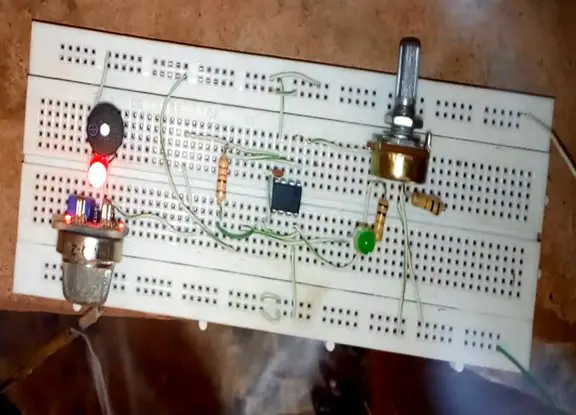
Figure 2.3 was taken while the circuit was being tested on the breadboard and in a smoky environment. The red LED is on, the buzzer is activated and indicated “SMOKE DETECTED”. This was as expected since the quantity of smoke had surpassed the environ.
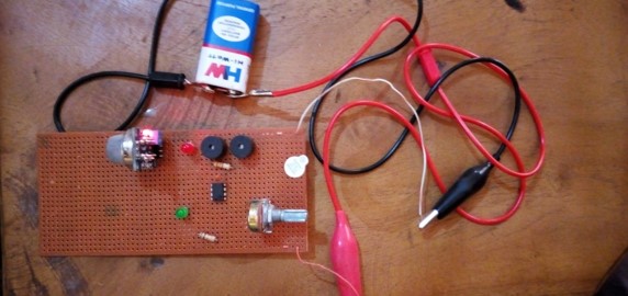
Figure 2.4 shows that the device has been transferred to Vero-board and the green LED is on, which means it is working perfectly. This device shows an additional need for buzzer which makes it two.
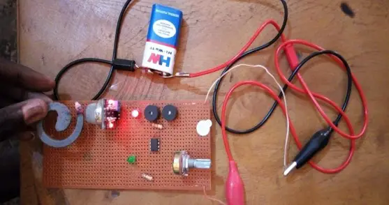
Figure 2.5 was taken during testing after the assembling on Vero-Board.
4.2 Cost Estimate and Evaluation
The following is the cost analysis of the materials used for this project:
Table 1.0: List of components and their prices.
| SN | Name of the Material | Quantity | Price (₦) |
| 1 | MQ2 Smoke Sensor | 1 piece | 3000.00 |
| 2 | LM358 | 1 piece | 500 |
| 3 | Vero Board | 1 piece | 200 |
| 4 | Jumper Wire | 4 pieces | 100 |
| 5 | Buzzer | 1 piece | 100 |
| 6 | LED (Red and Green) | 1 piece each | 100 |
| 7 | Resistors | 2 pieces | 150 |
| 8 | Capacitors | 2 pieces | 100 |
| 9 | Potentiometer | 1 piece | 100 |
| 10 | Bread Board | 1 piece | 500 |
| 11 | LEAD | 1 piece | 500 |
| 12 | Battery connector | 1 piece | 250 |
| 13 | Case | 1 piece | 50 |
| TOTAL | ₦5,650.00 |
Table 1.0 is the analysis of the materials/components used, the components used are of low cost with the same purpose of the high-cost material, the materials available in the local market. The total cost of the materials is ₦5,650.00 and can be sold at the rate of ₦7,000.00 which is of low-cost compared to the imported device which is sold at the rate of ₦60,000.00 for two (2) zoning (1 room capacity) or ₦90,000.00 for four (4) zoning (2 room capacity) which is costly.
SUMMARY, CONCLUSION AND RECOMMENDATION
5.0 Summary
In summary, the project work is to construct a device that detect presence of smoke and trigger alarm so as to warn the occupants of the location, it is a low-cost device and very efficient. It constitutes components which are cheap and easy to get. This device detects smoke at a close range and when placed in a good location it helps in detecting smoke early.
5.1 Conclusion
Human safety is a very crucial aspect in both domestic and industrial setting, hence use of smoke sensors is inevitable in addition to other more sophisticated security systems. From the discussion of the work above, it was observed that it detects smoke at the range of 5 meter and it detection rate depends on the range at which you place the controller, it uses low power and the battery used for the device has a long-life cycle, it is very small and not heavy. For efficient and good detection level it is advisable that the device should be mounted to the ceiling above the ground and in direction of the window where there is most likely to be the direction of the wind to facilitate the contact of the sensor with the smoke so as to be able detect fast enough and issue audible alert to the occupant of the premises. This work is done to help the people leaving in rural areas where there is no steady or lack of electricity especially the northern part of the country. The device is low-cost enough and affordable by the less privileged.
5.2 Recommendation
The following suggestions are for future research:
- Science-related students especially do that major in technical programs should be encouraged to partake in construction-related projects to boost the development of scientific achievements in Nigeria.
- Higher institutions should be provided with well-equipped technical workshops so as to enable students undergoing projects to have a suitable environment for their work.
- Increasing the range of detection and by making the device use both DC (Direct Current) and AC (Alternating Current) power supply and also make the battery rechargeable.
- More of this device should be produced massively so as to make each household have access to this device.
REFERENCE
- AEEE. (2014), ISSN 2231-1297, Volume 4, Number pp. 135-140© Research India Publications http://www.ripublication.com/aeee.htm
- Bhattacharya, P. (2002). “Semiconductor Optoelectronic Devices” (2nd ed.). New Dehli: Prentice-Hall of India Private Ltd.
- Bird, John (2010). “Electrical and Electronic Principles and Technology”. Routledge. pp. 63 76. ISBN 9780080890562. Retrieved 2013-03-17.
- Brazzell, D. (2012). “The Effects of High Air Velocity and Complex Airflow Patterns on Smoke Detector Performance” (PDF). AFCOM8-21.AFCOM-Miami Admin.com. Archived from the original (PDF). Retrieved 2009-05-13.
- “Carbon Dioxide – Life and Death” (2018). senseair.se. p. 4. Retrieved.
- Donal F. Steele and Robert B. Enemark (1975) “Optical Smoke Detector” US patent 3863076, issued.
- Elbehiery, H. (2012). “Developed intelligent fire alarm system”. Journal of American ScienceVol 8, Issue 8: 1016-1025
- Fleming, J. (2011) “Ion vs. Photo – Is There A “Qualitative” Difference For LifeSafety” Retrievedfrom:http://www.mass.gov/eopss/docs/dfs/osfm/boards/specificmeetings/jfming/deputy-chief-joseph-fleming-mass-summit-overheads.pdf.
- Fleming, Jay. (2016) “Smoke Detector Technology Research” Archived at the Wayback Machine, retrieved 2011-11-07
- Floyd, Thomas (2005). “Electronic Devices” (7th ed.). Upper Saddle River, NJ: Pearson Education. p. 10. ISBN 0-13-127827-4.
- Francis Robbins Upton. “Smoke alarms in U.S. Home Fires.” (2015). nfpa.org.
- George Andrew Darby, (1902) “An Electric Heat Indicator and Fire-alarm” GB805,
- “How smoke detector is made”. (2014). Retrieved from Madehow.com Advameg.
- International Advanced Research Journal in Science, Engineering and Technology Vol. 2, Issue 5, May 2015 ISSN (Online) 2393-8021.
- International Journal of Computer and Electrical Engineering, (2013) Vol. 5, No. 2.
- International Journal of Computer Trends and Technology (2018) – Volume 58 Issue 1 IJCTT
- International Journal of Engineering Science and Computing, (2018) Research Article Volume 8 Issues No.3
- International Journal of Innovative Research in Computer and Communication Engineering (2016) (An ISO 3297: 2007 Certified Organization) Vol. 4.
- International Journal of Scientific and Research Publications (2014), Volume 4, Issue 7, ISSN 2250-3153
- International Journal of Scientific and Research Publications, (2014) Volume 4, Issue 7 ISSN 2250-3153
- IOSR Journal of Electrical and Electronics Engineering (2017) IOSR-JEEE e-ISSN: 2278 1676, p ISSN: 2320-3331, Volume 12, Issue 6 Ver. III, PP 4248 www.iosrjournals.org.
- IOSR Journal of Electrical and Electronics Engineering (2017) IOSR-JEEE e-ISSN: 2278 1676, p ISSN: 2320-3331, Volume 12, Issue 3 Ver. II, PP 4753 www.iosrjournals.org.
- National Fire Protection Association. (2013). NFPA 72: National Fire Alarm and Signalling Code.
- New York City Fire Department. (2012) “Carbon monoxide alarms”. Archived (PDF).
- Prosser, Richard. (1970) “Birmingham Inventors and Inventions”. H.M. Patent Office (originally 1881). S.R. Publishers. ISBN 0-85409-578-0.
- Punam P. and Shamik T. (2012) “International Journal of Computer Applications ”Volume 58– No.18, P 0975 – 8887.
- Quackenbush, F. (2015) “Smoke Alarms in Building Construction/Interviewer” J. Williams.
- Schubert, E. F. (2010). “Light-emitting Diodes”. (2nd ed.) Cambridge University Press, Cambridge.
- Shin, J. C., Chris H., Kristen A. P., and André M. (2007), “Fire detection using smoke and gas sensors” Final Manuscript submitted to the Fire Safety Journal.
- Suneel Mudunuru et al, (2011) International Journal of Computer Science and Information Technologies, Vol. 2 (6), 2011, 2531-2540 ISSN: 0975 9646
- The Authoritative Dictionary of IEEE Standards Terms (IEEE 100) (seventh ed.). Piscataway, New Jersey: IEEE Press. 2000. ISBN 0-7381-2601-2.
- The New York Times. (2011) The New York Times Company. Retrieved.
APPENDIX A: MQ2 GAS SENSOR CONNECTION DIAGRAM
APPENDIX B: LM358 BLOCK DIAGRAM
APPENDIX C: POTENTIOMETER BLOCK DIAGRAM

I am really happy for completing this project and I will like my project to be used for further development.
Great work Suleiman Abdulhameed Bashir.
Thank you sir.
How did you come up with the values for all your components? I’d really love to understand your project further
Good day.
Can you you please explain how you came up with your values for the components, how you chose each of them?
Your project is really beautiful and i’d like to understand it further
Hi Gloria, thank you for contacting me and sorry for the late reply, regarding your question, the values were gotten during simulation, after the design and knowing the components needed, you go for simulation where you test the components and the values needed. Thank you.