ABSTRACT
On this Earth’s landmass there existing wheeled and tracked vehicles. But people and animals using their legs can go almost anywhere. The main aim of the walking mechanism is to develop rough terrain robots by capturing mobility autonomy and simulation of living creatures. Such robots can travel like living creatures in stepped stairways household clutters limit the utility of wheeled vehicles. Machines consist of a number of mechanisms for their successful operation and to give the desired output. Mechanisms like four-bar mechanism, single slider crank mechanism, double slider crank mechanism, etc, are used for transmitting motion, force, torque etc.. Our aim is to perform analysis on that walking mechanisms to study kinematic motion, stresses & deformations in the kinematic links by Using CAD software. The analytical data can be used for reference purpose to design a walking robot to attain better design qualities. There are many types of walking mechanisms but there are two major mechanisms implemented to their best. They are THEO JANSON’s mechanism and KLANN linkage. So we are going to perform analysis on KLANN linkage. KLANN linkage is an expansion of four-bar mechanism. It was first developed by Joe Klann in 1994. The analysis is based on the FEM concept integrated into CAD software called ANSYS 16.0. And also by using a designing software called CATIA, we are going to design a 3D model of the walking form and simulate them.
SYNOPSIS
Objective:
To design the model of a walking robot by using SOLIDWORKS and to do analysis on the kinematic links of leg mechanism by using ANSYS.
Project Eye:
- In order to observe the stress distribution in the kinematic links of leg mechanism to get a safe design of walking robot.
- To know the velocity and acceleration of each kinematic link in leg mechanism.
- To observe the simulation of walking robot
- To get the flexible design of walking robot by the simulation in SOLIDWORKS by using default dimensions from KLANN mechanism
Future Scope:
The project is dealing with the analysis and design of the walking robot. But our future prospect is to replace the wheels with the leg locomotion in terrain robots to go anywhere where the wheels cannot go.
1 INTRODUCTION
1.1 Klann Mechanism
The Klann linkage was developed by Joe Klann in 1994 as an expansion of Burmester curves which are used to develop four-bar double-rocker linkages such as harbour crane. This Klann mechanism is a planar mechanism converts the rotary motion of the crank to linear movement of the foot for one-half rotation of the crank and raises the foot for the second half, returning it to the starting point. Two of these linkages, 180 degrees out of phase, will function as a wheel replacement. It was designed to simulate the gait of legged animal like spider and function as a wheel replacement. Here the wheels can be replaced by either four legs or six legs sometimes eight legs is also possible to design a terrain robot. The Kann linkage consists of the frame, a crank, two grounded rockers, and two couplers all connected by pivot joints. It has 6 links per leg.
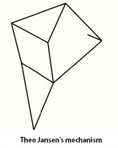
There is also another popular mechanism is also there that is Theo Jansen’s mechanism. Which designed by Theo Jansen to simulate a smooth walking motion. Jansen has used his mechanism in a variety of kinetic sculptures which are known as Strandbeests. Jansen’s linkage bears artistic as well as a mechanical merit for its simulation of organic walking motion using a simple rotary input. There are many types of leg mechanisms are there such as Eight-bar leg mechanism, Strandbeests (applied Jansen linkage), Tokyo Institute of Technology walking chair, Ghassaei Linkage Tchebyshevs plant grade machine. But out of them, Klann mechanism and Jansen mechanism are most popular and best in design.
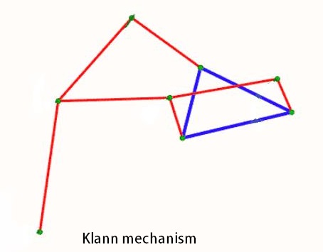
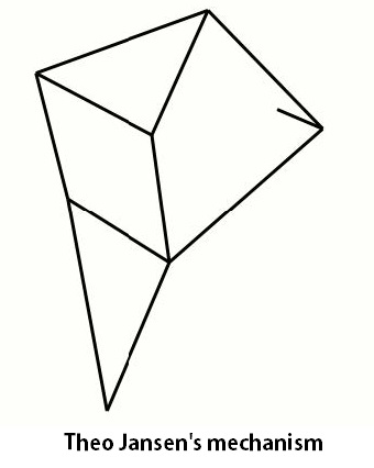
The above Pictures shows how the links connected to other links and how they can simulate. Klann mechanism is somewhat better in design because of their less number of links as compared to Jansen’s linkage. That’s why we would like to choose computer-aided design and analysis of walking robot based on Klann mechanism by using some CAD tools. These walking robots can go anywhere like living organisms like terrain areas and rocky areas and muddy surfaces.
1.2 Walking Robots
As the wheels are ineffective on rough and rocky areas, therefore robot with legs provided with Klann mechanism is beneficial for advanced walking vehicles. It can step over curbs, climb stairs or travel areas that are currently not accessible with wheels. The most important benefit of this mechanism is that it does not require microprocessor control or a large number of actuator mechanisms. In this mechanism, links are connected by pivot joints and convert the rotating motion of the crank into the movement of foot similar to that of animal walking. The proportions of each of the links in the mechanism are defined to optimize the linearity of the foot for one-half of the rotation of the crank. The remaining rotation of the crank allows the foot to be raised to a predetermined height before returning to the starting position and repeating the cycle. Two of these linkages coupled together at the crank and one-half cycle out of phase with each other will allow the frame of a vehicle to travel parallel to the ground. This project is useful in hazardous material handling, clearing minefields, or secures an area without putting anyone at risk. The military, law enforcement, Explosive Ordinance Disposal units, and private security firms could also benefit from applications of a mechanical spider. It would perform very well as a platform with the ability to handle stairs and other obstacles to wheeled or tracked vehicles.
This walking robots can be more advantageous than wheeled robots and can go anywhere like as humans and other organisms like spider and crab and cockroach. There are so many types of walking robots.
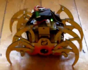
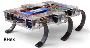
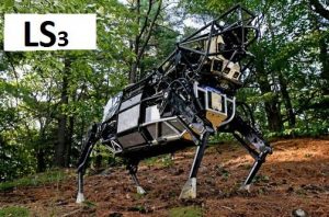
That above picture shows the some of the walking robots which are developed For rough terrain areas.
1.3 Advantages of Walking Robots over Wheeled Robots
- Legged robots or vehicles can navigate on any kind of surfaces which is inaccessible to robots with wheels.
- Legged robots can jump or step over obstacles whereas wheels need to somehow travel over it, or take a different path
- Wheels require a continuous path to travel whereas legs can step over isolated paths and move on.
- Legged robots can avoid undesirable footholds which cannot be avoided in a wheeled robot
- Legged robot helps us in exploring human and animal locomotion
- Once we move off from our modified habitat into rough, rocky, sandy, steep and undesired terrain, we understand that our brilliant invention of wheels turn out absolutely useless
- Lastly, the excitement of replicating a human or an animal and try to challenge nature
2 LITERATURE REVIEW
Figure in the previous page shows the leg mechanism, using a Klann mechanism to imitate the spider (insect) leg. The project going to choose a six-bar mechanism because of its superior force-transmission angle and bigger oscillating angle in comparison with other types such as the Theo Jansen’s mechanism. Force transmission is very important for leg mechanisms, because of the point contact with the ground. The leg mechanism, with its body size shown in Figure mentioned in the previous page. It has six links and seven cylindrical joints. The body size and link dimensions are determined from the maximum swing and lift angles so that’s why the project considering the default dimensions for Analysis.[1]
Transporter vehicles have traditionally used wheel Mechanisms like cars and trains. Wheels are ideally suited for movement without vertical fluctuations of the body, and tires with inner rubber tubes absorb shock from a rugged road. On the other hand, biologically-inspired robotics learn mobile flexibility from the living creatures of multiple legs and their coordination. Good examples of this are arthropods, like spiders and cockroach and the robots are conventionally designed with actuators placed in every joint.[2] In such implementation, robots are good tools to investigate how an animal moves,[4] but they are unable to be a substitute principle for wheels because they don’t much take into account the maximum load capacity. Joint’s actuators promise mobile flexibility, while the Actuator’s torque performance impacts on the toughness of the robot’s body. Therefore, in the design of disaster robots, which need to move on rubble and carry rescue devices, continuous tracks or crawlers are popular. Theo Jensen a Dutch kinetic artist who has attempted to create a bridge between art and engineering by focusing on biological nature, proposed a linkage mechanism to mimic the skeleton of animal legs. This is called “Theo Jansen mechanism,” and provides the animal with a means of moving in a fluid manner.[5] Interestingly, his artificial animals require no electric power for actuators and do work by weak wind power to drive the gait of multiple legs through a transformation of internal cyclic motion to an elliptical orbit of the legs. This has a name Strandbeests. Which means Beach animal the following figure shows how it looks exactly
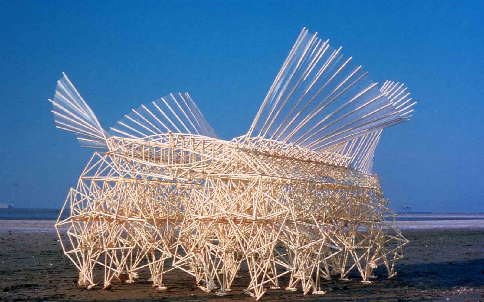
Pic: from learningfromdogs.com
Behind that gait structure of STRANDBEEST, the mechanism involved is Theo Jansen’s mechanism. Each individual leg structure is placed side by side to form that structure. Theo Jansen’s mechanism is also sown in the previous page once again sown here.
3 KLANN MECHANISM
Klann mechanism is a planar mechanism converts the rotary motion of the crank to linear movement of the foot for one-half rotation of the crank. There are six links in Klann mechanism they are fixed frame, crank, upper rocker arm, lower rocker arm, and connecting arm main leg link.
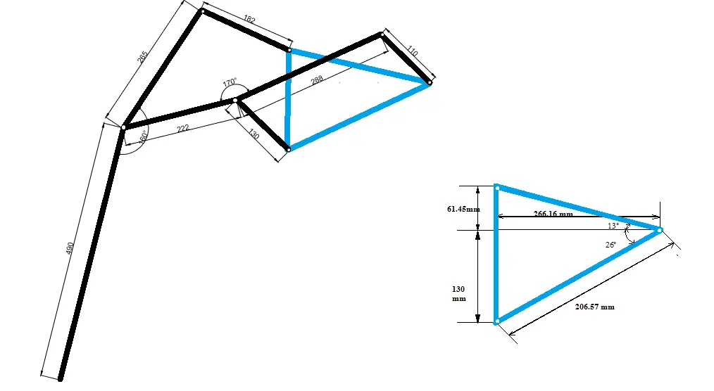
Fig 3.1: Klann linkage
Our objective is to perform analysis on Klann mechanism and to design a computer model of walking robot to demonstrate a walking robot based Klann mechanism. The computer model is showing how the six-legged robot can be designed and how it can be simulated. Our project is going to simulate the computer model and perform analysis on the single leg of the walking robot based on Klann linkage by using FEM concept. There are so many CAD tools to perform this analysis. By using one of the CAD tools the project is going to work on it.
There are So many CAD tools like SOLIDWORKS, CATIA, CREO, UNIGRAPHICS, AutoCAD, ANSYS, and ABAQUS. Each software has its own style of designing and analysis procedures.
The project is completely based on those CAD tools. So we are going to choose the one which has more flexible to us in designing and Analysis. But unfortunately both design and Analysis is not easy with a single software. That’s why we are going to choose individual software for design and analysis. First of all the computer model of walking robot based on Klann mechanism is going to perform in SOLIDWORKS. Because of its user-friendly interface and very easy to learn about designing tools in SOLIDWORKS and good graphics interface when compared to other software.
Coming to Analysis which is also possible in solid works but ANSYS is the best software for analysis. But solid works also can do the analysis but the problem is accuracy. In SOLIDWORKS the results are less accurate but in ANSYS we can get more accurate values than SOLIDWORKS. And also meshing technics are also more in ANSYS compared to SOLIDWORKS. But SOLIDWORKS takes less time to solve the model but ANSYS takes more time than SOLIDWORKS.
3.1 DIMENSIONS AND PATH TRACKING ON LEG
As said earlier The project is stick to the default dimension for the Klann mechanism from the Klann website to do analysis and CAD model walking robot.[3] But now the project is going to check out the changes the dimensions of the legs and want to observe the change in the path traced by the point where the main leg link touched with the ground.
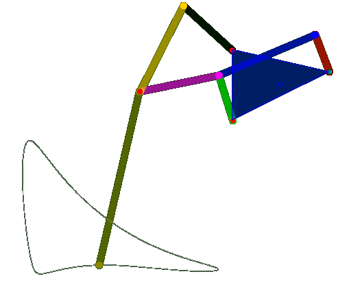
Fig 2.3: No dimension changed
In the above picture, the path traced by the point on the main leg link of Klann mechanism is shown how the leg moving forward and backwards. Here there are no changes done in the dimensions of any link of the leg mechanism.
If any changes made in Connecting arm then the path traced by the point on main leg link changes. That is shown in the following figure 2.
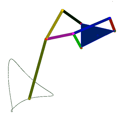
Fig 2.4: Dimensions changed in the Connecting arm
In the above figure shows that how the path traced by the point on the main leg link. The path is little twisted when it is touching the ground so that the flexibility and stability of the leg are changed and it is not suitable for the design of walking robot.
Now the project is going to change the dimensions of the crank. Then the path traced by the point on the main leg link will definitely change as shown in below figure 3
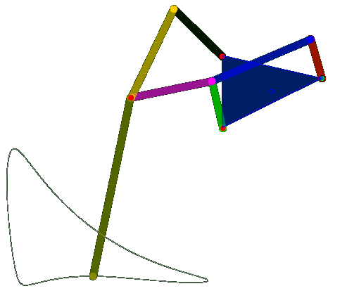
Fig 2.5: Change in crank dimensions
The path traced by the point on the main leg link is shown above. It is similar to the first fig 1 but here the project cannot observe the motion of the main leg link. If we see the motion of the main leg link, there is a difference between the motion velocity. similarly, if the project changes the dimensions of the upper rocker arm and lowers rocker arm then the project can observe the same phenomenon in the motion velocity.
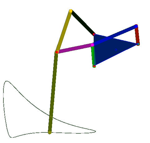
Fig 2.6: Changes made in the lower rocker arm
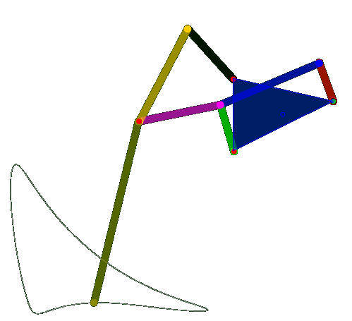
Fig 2.7: Changes made to main leg link
4 INTRODUCTION TO SOLIDWORKS
SolidWorks is a modern computer-aided design (CAD) program. It enables designers to create a mathematically correct solid model of an object that can be associated with the properties of the materials used, the project can get a solid model that can be used to simulate and predict the behaviour of the part or model with finite element and other simulation software. The same solid model can be used to manufacture the object and also contains the information necessary to inspect and assemble the product. The marketing organization can produce sales brochures and videos that introduce the product to potential customers. SolidWorks and similar CAD programs have made possible concurrent engineering, where all the groups that contribute to the product development process can share information in real-time.
SOLIDWORKS is user-friendly software which is easy to learn and understanding. And much easier to use. Compared to other CAD software like CATIA this software is much easier to use. It was first developed in 1993 and the first release is in 1995 y DASSAULT systems. Dassault systems also developed CATIA which is also a great software which is more effective and powerful CAD software
In SOLIDWORKS there are mainly three modules when we open a new file. They are part modelling, Assembly modelling and Drafting. In part modelling there is a different kind of additional modules are there like surfacing, sheet metal, sketcher, mould tools, Weldments and office products.
4.1 MODELING OF WALKING ROBOT BASED ON KLANN MECHANISM
The design of walking robot is based on our size of bot width and height and length. Which is optional for choosing the dimension of the bot whether the bot is bigger in size or smaller. According to that, the project can change that dimensions of the Klann mechanism. So the project is not going to change that dimensions of Klann mechanism. The project considering the true dimensions for leg and based on that dimensions the project changing the dimensions of bot to avoid difficulties in designing of the entire walking robot.
So the project is considering the length and height and width of the robot according to the length of the leg. These dimensions are only considerations. Not fixed.
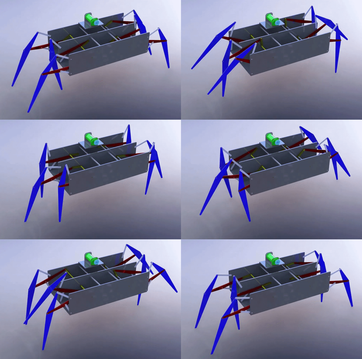
4.2 OBSERVATION
Those all above pictures are taken while designing of walking robot in SOLIDWORKS. The above model can be simulated how the walking robot can walk. But according to the above model the project can simulate only forward and backward direction only. Because two legs of the robot are mounted on the single frame. That’s why the robot cannot take any turns. But it is needed to each leg should be mounted on individual frames and those should have free DOF along the horizontal direction. Then the robot can easily get turnings for the six-legged robot. But the power transmission for each individual leg in control gear ratio. This can be achieved by the sensors and actuators. Then the project can design a successful six-legged walking robot which can go anywhere like living creatures like crab and spider. Actually, this kind of robots called as Mechanical spiders. This name was already given by the Klann in their official website. But they are designing legged robots consisting of four legs. That could be more advantageous than six-legged because of less number of joints and links will result in less friction.
In our there is only one motor is mounted on the frame. The project can also mount individual motors for the individual cam. i.e. One motor for back three legs and a second motor for front three legs. But the motors should follow the same gear ratio. Otherwise, the project cannot get the walk for the robot. This will helps to take turnings when the two motors rotating in a reversed direction. And in the same direction will result in forwarding or backward moment.
5 INTRODUCTION TO ANSYS
ANSYS is an engineering simulation software. Which was developed by the ANSYS, Inc Headquarters is located in Pittsburgh in Pennsylvania, United States.
Which provides so many products like ANSYS Mechanical, Auto Dynamics, Ansys fluid dynamics, CFD, CFX, Electronics, ANSYS Maxwell and similar products. In each product there are so many internal modules are there. Like in mechanical there are structural and linear and nonlinear and thermal, transient analysis and explicit analysis. So Ansys provides a different kind of platforms for the different type of analysis.
ANSYS was founded in 1970, John A Swanson. Which is first developed for structural physics that could simulate static i.e. stationary and dynamic i.e. moving and thermal analysis. After that, they release so many versions with different products like mentioned above. Now present version is ANSYS 17.0 but which is not available yet. But there is a free license for student edition named ANSYS 16.2. Which gives a free license for six months for students on commercial use. That’s why the project would like to go with this version. But this version has limitations like the number of nodes/elements should not exceed 32,000 for structural and for fluent 512,000 nodes/elements. If that limit is crossed then the Ansys 16.2 cannot solve any problem. So we should make sure about the number of elements not to exceed 32,000. Mainly the analysis is going to proceed in two different modules. One is rigid analysis and another one transient structural analysis. In the rigid analysis, the project can get the velocities and accelerations of the links. In the transient structural analysis, this will gives the stress, strains, and deformations. Now, all we need is input information for the analysis. Above those two analysis procedures requires two different input information.
Before going to the analysis we are considering only one leg fixed to the frame. i.e half the frame length will be considered in the analysis of Klann mechanism. This will reduce the complexity of the analysis and reduce the number of the elements. This results in analysis time.
For analysis process the project considered that to fix a DC motor of 30 rpm with 5 kg torque. This is only to consider the input information for ANSYS. i.e for dynamic analysis, it should have a input information for ANSYS. By this 30 rpm speed of the motor, this will give the angular velocity of the crank by the formula for angular velocity. Here the motor power is directly transferred to the crank.
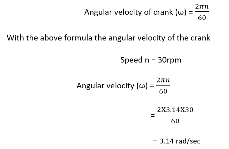
Now the project needs to find out the time taken for the crank to complete one rotation from given speed of the motor. Because the project is going to do the transient analysis. i.e time-based action to find out the velocities of each link in Klann mechanism.
30 rotations = 60 seconds
1 rotation = 2seconds
Time taken for one rotation of the crank is = 2 sec
5.1 STRUCTURAL ANALYSIS
Now the previous data is enough for the rigid dynamic analysis. The rigid dynamic analysis will give us the linear velocities and angular velocities and joint reactions of each leg link in leg mechanism with this input information.
And there the project can also be going to finding out the stress in links of the leg mechanism and deformations and fatigue analysis. In fatigue analysis, the project can find out the life, damage and the safety factor.
This transient structural analysis requires torque for the crank. i.e how much amount of torque is produced by the motor and transmitted to the crank.
Torque = 5 kg-cm
= 490.5 N-mm
= 0.4905 N-m
The above value is the input for the transient structural analysis. The value should be input as the joint load at the joint between the crank and the frame. The results are shown in the following pictures shown in the further pages. First, the pictures of the transient structural analysis results are shown.
5.1.1 SAMPLE IMAGES
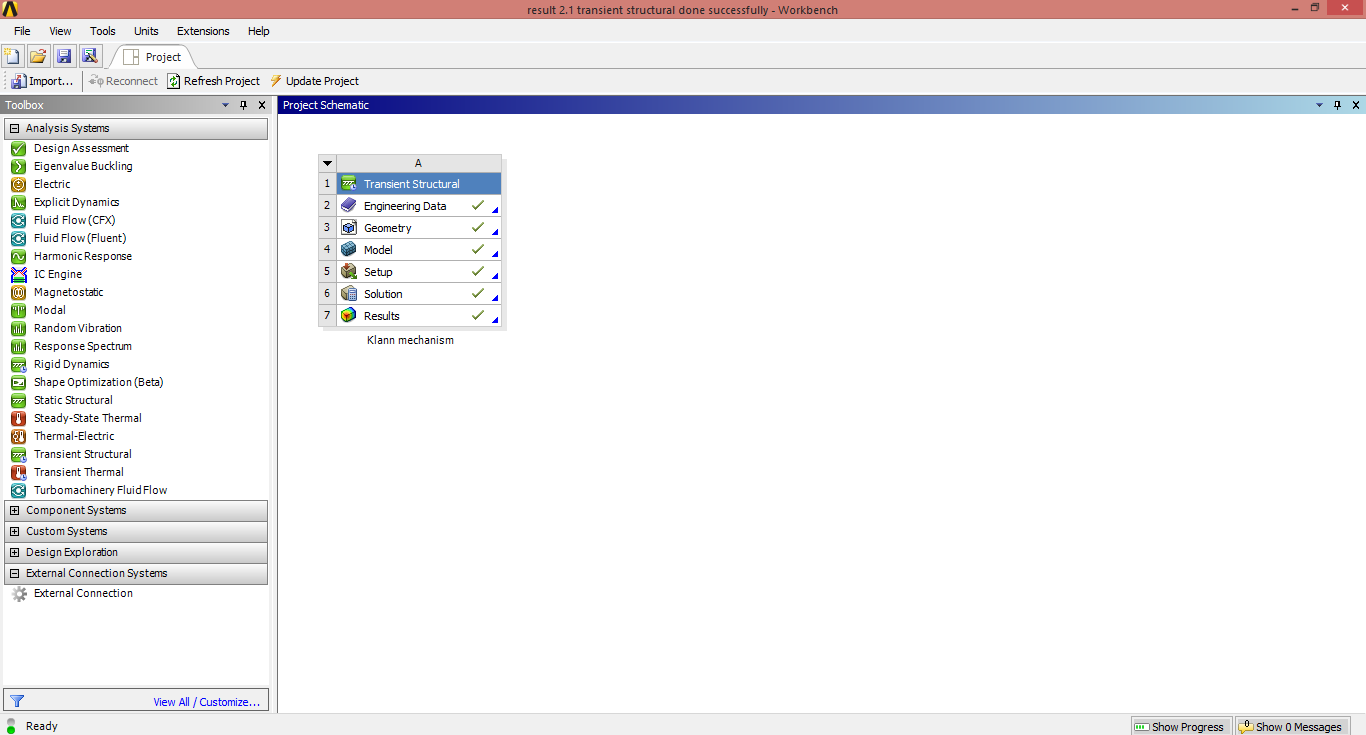
Fig 5.1: ANSYS Workbench 16.2 interface
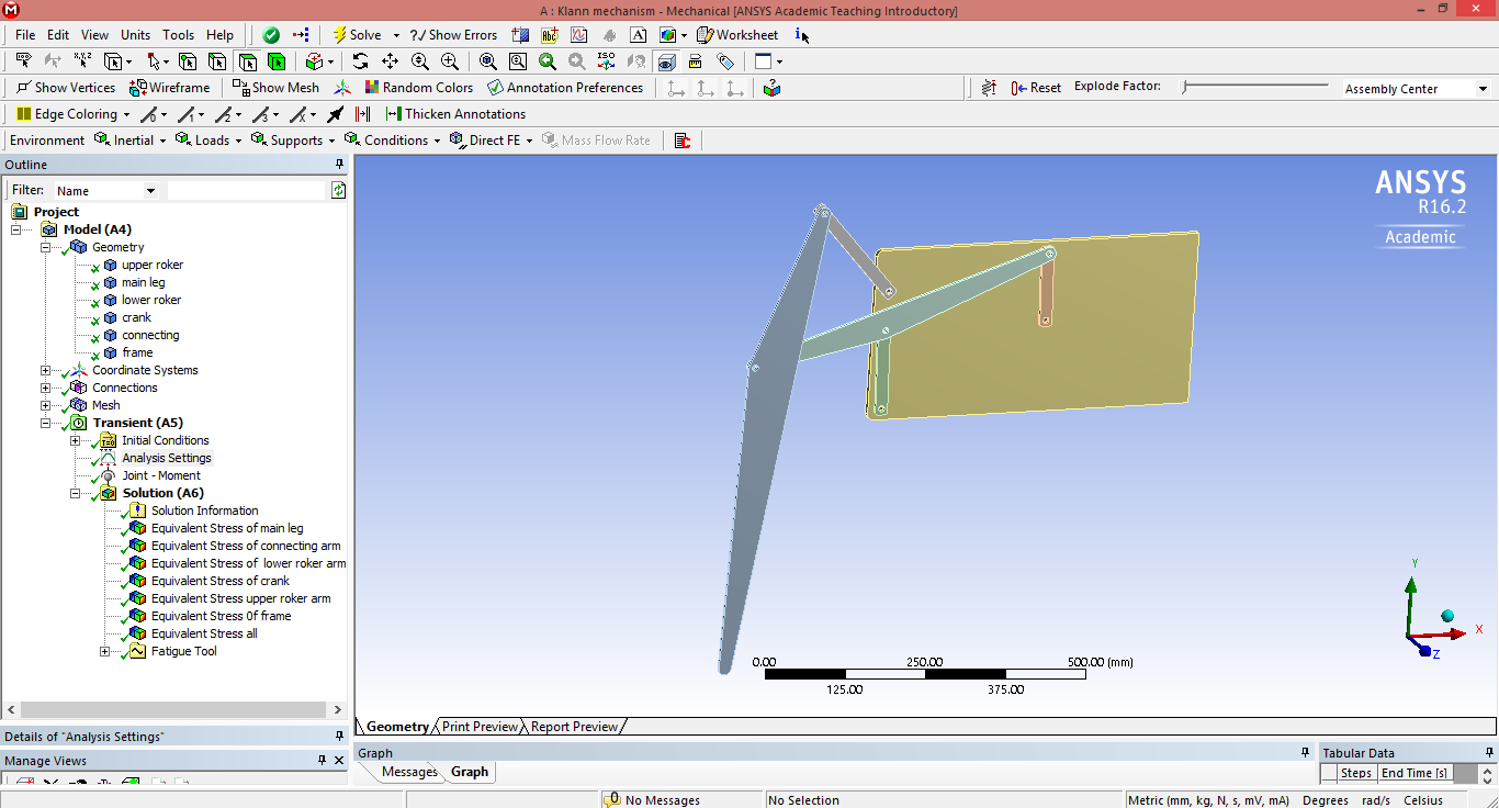
Fig 5.2: ANSYS mechanical module
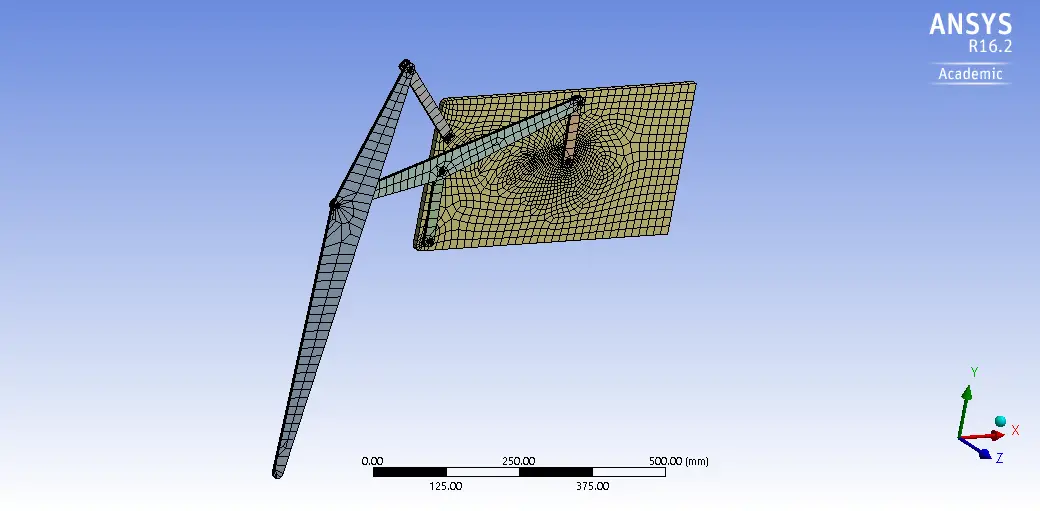
Fig 5.3: Meshing
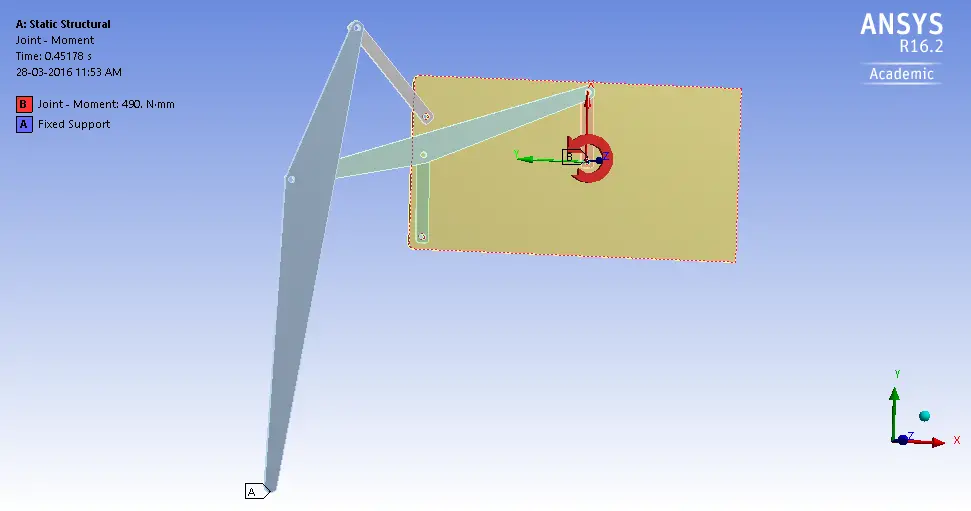
Fig 5.4: Boundary conditions
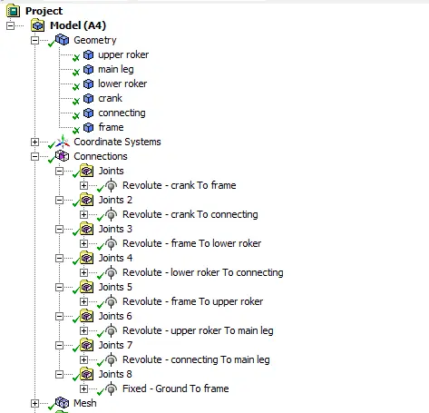
Fig 5.5(a): Product tree
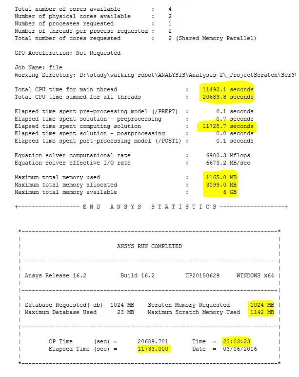
Fig 5.5(b): Solution information
The results of structural analysis of the mechanism are shown in the following figures. Results can be understood by the colour coding in Ansys. The following figure 4.6 shows the equivalent stresses in main leg link. Here the blue colour represents the minimum value and red colour represents the maximum value as the colour bar shows the respected value according to the colour. In the main leg, the maximum stress is obtained at the point where the link contacts with the ground so here there may be more deformation so to avoid this deformation we need to make it stronger by adding material there. This will helps to avoid stress there but the stress will be transferred to another point. So the material to be added thereto transfer some amount of stress not to avoid stress.
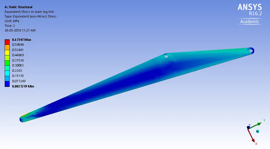
Fig 5.6: Equivalent stress in the main leg
The stress distribution in the connecting arm shown in the following figure 4.7. It will show the equivalent stress in connecting arm here the colour bar shows the respected stress values for the connecting arm. Here the stresses are the compressive stresses. Because the stresses are more at the points where the pivots connected to the main leg link and crank.
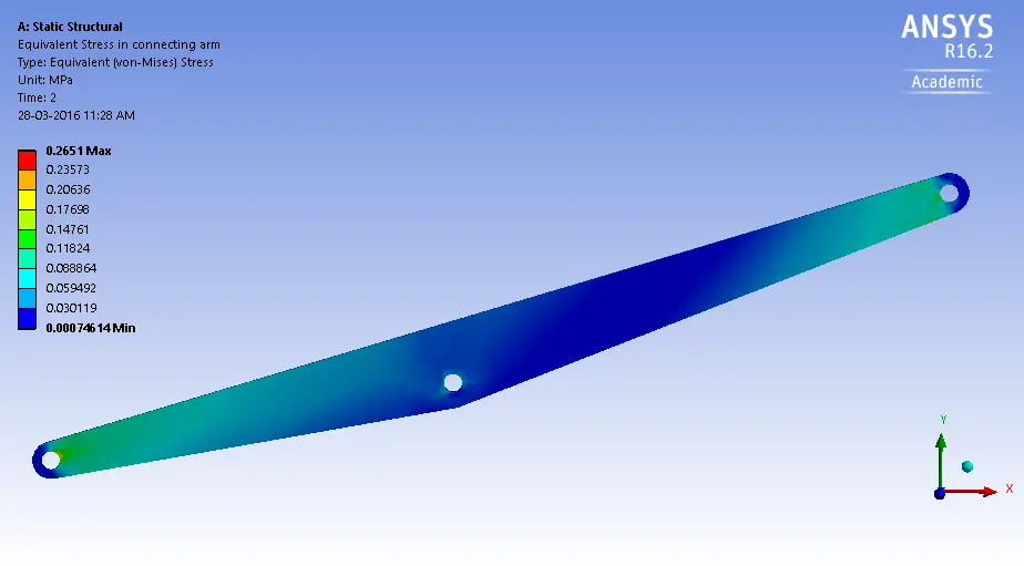
Fig 5.7: Equivalent stress in connecting arm
Fig 5.8 shows the stresses in lower rocker arm here the colour bar shows the stress values of the lower rocker arm. Here also the stresses more are at the pivot points but these stress values are very less compared to the other components.
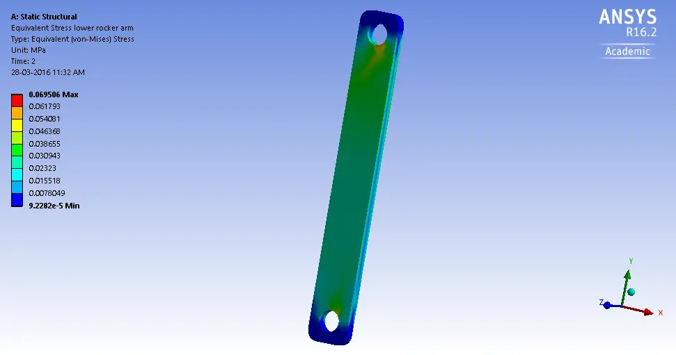
Fig 5.8: Equivalent stress in the lower rocker arm
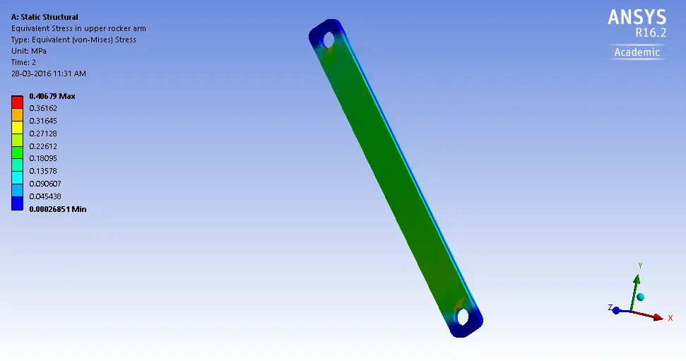
Fig 5.9: Equivalent stress in the upper rocker arm
The stresses in the crank are more compared to the other components because this the link mounted on the shaft of the motor. So this link is responsible for the entire motion in the leg mechanism. So the stresses are observed more compared to the other components this stress are shown in fig 5.10
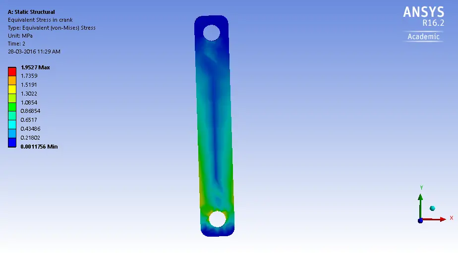
Fig 5.10: Equivalent stress in the crank
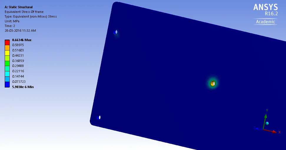
Fig 5.11: Equivalent stress in the frame
The stress in the frame is also shown in the fig 5.11 here also the maximum stress is at the hole where the crank and the motor shaft connected. Fig 5.12 shows the entire stress distribution in the mechanism.
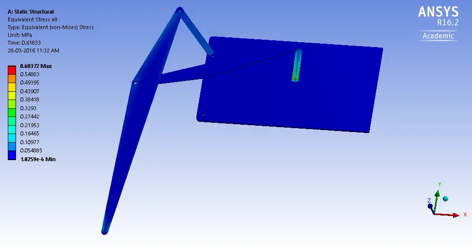
Fig 5.12: Equivalent stress in entire mechanism
5.1.2 OBSERVATIONS-1 IN THE TRANSIENT STRUCTURAL ANALYSIS
In those above picture shown the equivalent stress of the links for the given input information. Figure 5 shows the stress distribution along the main leg link. Next figure 6 shows the stress distribution in connecting arm likewise the further pictures shows the respected stress distribution in the remaining links.
The maximum stress produced in the whole mechanism is in the crank and is noted 1.9Mpa and the minimum stress is produced in lower rocker arm which is noted as 0.066Mpa. Actually, the minimum stress produced in the frame as 43Mpa but the project are considering only the six links of Klann mechanism.
Equivalent stresses in main leg link = 0.67Mpa
Equivalent stresses in connecting arm = 0.27Mpa
Equivalent stresses in crank = 1.95Mpa
Equivalent stresses in lower rocker arm = 0.069Mpa
Equivalent stresses in upper rocker arm = 0.40Mpa
Equivalent stresses in frame = 0.66Mpa
5.2 DYNAMIC ANALYSIS
For analysis process, the project is going to fix a DC motor of 30 rpm with 5 kg torque. This is only to consider the input information for ANSYS. i.e for dynamic analysis, it should have a input information for ANSYS. By this 30 rpm speed of the motor the angular velocity of the crank by given the formula for angular velocity. Here the motor power is directly transferred to the crank.

Now the project needs to find out the time taken for the crank to complete one rotation from given speed of the motor. Because the project is going to do the transient analysis. i.e time-based action to find out the velocities of each link in Klann mechanism.
30 rotations = 60 seconds
1 rotation = 2seconds
Time taken for one rotation of the crank is = 2 sec
That above information is used to find out the angular velocity and linear velocities of the links and also this will helps to find the accelerations of the links. The following pictures will show us the results of the rigid dynamic analysis. The dynamic analysis can be done in two ways. In both transient structural and Rigid Body Dynamics. But the project completed that analysis in both modules and the got the values. The following picture is posted in following pages
5.2.1 SAMPLE IMAGES – 3
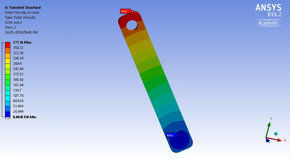
Fig 5.13: Velocity in the crank
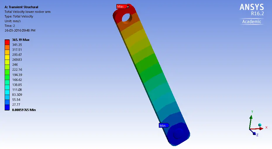
Fig 5.14: Velocity in the lower rocker arm
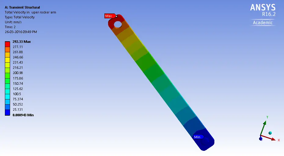
Fig 5.15: Velocity in the upper rocker arm
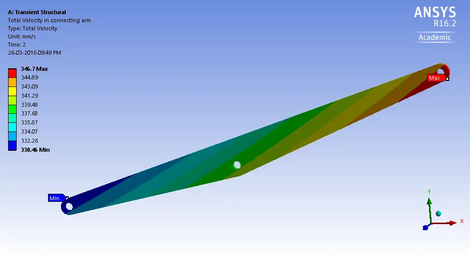
Fig 5.16: Velocity in connecting arm
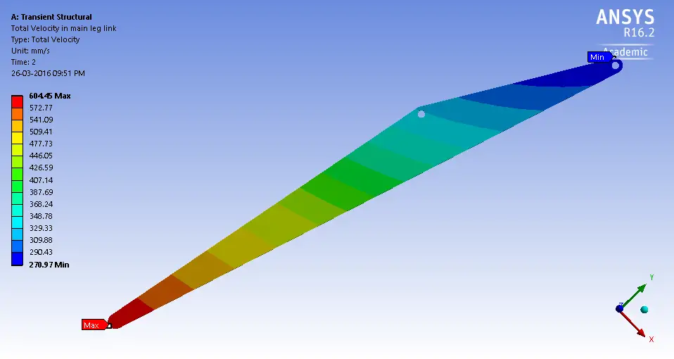
Fig 5.17: Velocity in main leg link
Fig 5.13 to fig 5.22 show the results of the dynamic analysis of the project. Here dynamic analysis gives the total velocity and accelerations of each link in the mechanisms. In the above from fig 4.20 shows the total velocities of the links. Here the maximum velocities found at the point which is in contact with the ground. Here the above colour coding represents the velocities of the link. Blue represents the minimum velocity and the red represents the maximum velocity. And the remaining colours represent the respected velocity values in the colour bar side of the picture as shown above.
The following figures are the results of accelerations in the links. The dynamic analysis also gives this acceleration in the links. Here also the accelerations are more as same as the velocities in the main leg link where the leg contacting with the ground. The following fig 5.18 to fig 5.22 show the accelerations in the links. In observation 3 the project has discussed the velocities and accelerations.
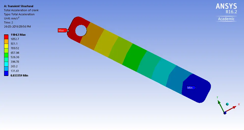
Fig 5.18: Acceleration in the crank
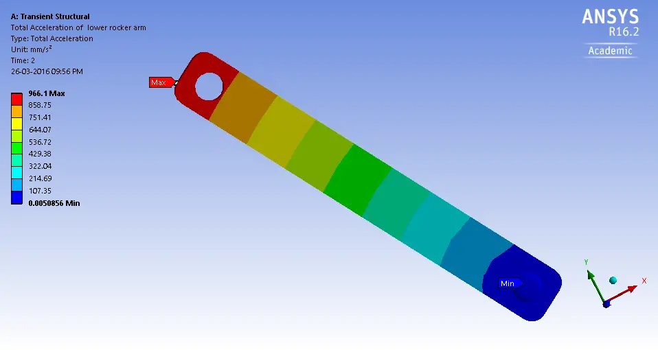
Fig 5.19: Acceleration in the lower rocker arm
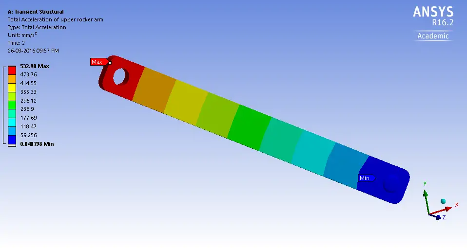
Fig 5.20: Acceleration in the upper rocker arm
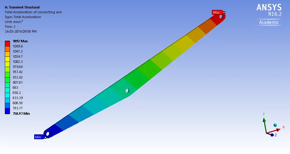
Fig 5.21: Acceleration in connecting arm
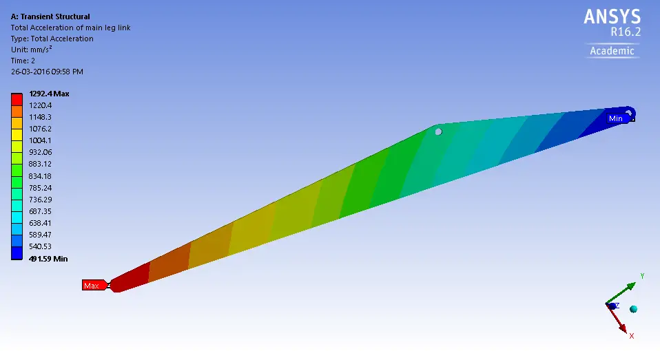
Fig 5.22: Acceleration in main leg link
5.2.2 OBSERVATION-3 FOR DYNAMIC ANALYSIS
The above figures show that the results from the dynamic analysis of the leg mechanism. Here the project got the total velocity of the links and the total accelerations of the links. The project is only calculating the velocity and accelerations of the links by theoretical calculations. First five figures show the velocities of the links and the remaining shows the accelerations.
The maximum velocity produces is in the main leg link where the point touches with the ground. This point has the maximum velocity. And the minimum velocity is in the upper rocker arm. The maximum acceleration is also produced in the main leg link where the point touches with the ground. And the minimum acceleration is in the upper rocker arm.
6 THEORETICAL CALCULATIONS FOR DYNAMIC ANALYSIS
Finding velocities for kinematic links: first, the project needs to find out the velocity of the crank. After that, the project needs to find the velocities of the remaining links by using the velocity diagram method.

Linear velocity (v) = ω r m/sec
= 3.14 X 110 X
= 0.3454 m/sec
Relative velocity method (graphical):
Scale 1cm = 0.3454/3 m/sec
= 0.11513 m/sec
(Note: the graphical method for velocity diagram are drawn in CAD software to get more accurate results and angles to avoid parallax errors)
Velocity diagram construction with CAD tools:
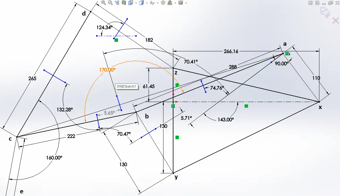
Fig 5.1: perpendiculars to the respected links
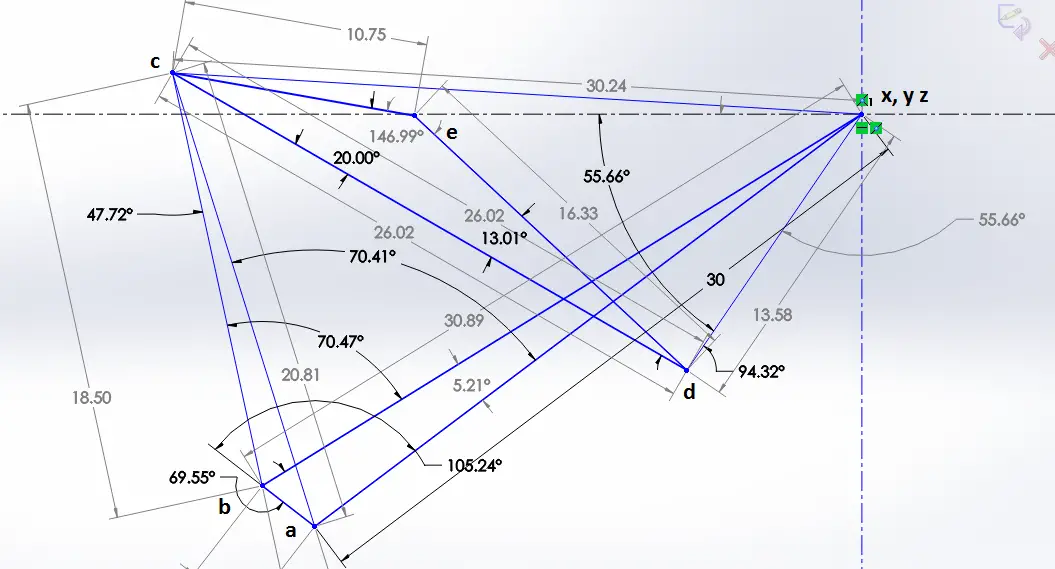
Fig 5.2: velocity diagram with dimensions
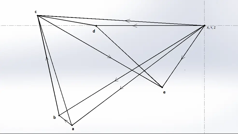
Fig 5.3: velocity direction
The velocity of link XA (Va) = 0.3454m/sec
By using scale factor mentioned above convert them into velocities
Velocity of link AB (Vb/a) = 0.29X0.11513
= 0.0333m/sec
Velocity of link YB (Vb) = 3.09X0.11513
= 0.35575m/sec
Velocity of point C (Vc) = 3.024X0.11513
= 0.348m/sec
Velocity of link DZ (Vd) = 1.358×0.11513
= 0.156m/sec
Velocity of link CD (Vcd) = 2.602X0.11513
= 0.299m/sec
6.1 DISCUSSIONS
Those above results are approximately matched with our theoretical results. But some difference is there because of the lengths and thickness of the frames the project cannot avoid the holes for joints and thickness in design.
And the comparison between theoretical and ANSYS results are shown in table 7.1 and table 7.2. There is a big difference in some links like upper rocker arm and main leg link are not matched but the remaining are nearly reached. So the problem is in theoretical calculations. So that the project is got the right results from ANSYS but due to some mistakes in theatrical calculations we got less accurate results from theoretical calculations. This is what the project observed from the Analysis.
7 RESULTS COMPARISON
Comparisons involved comparing the results of analytical data with the theoretical values. Here the project observed that velocities and accelerations of the links and accelerations of each link in the walking mechanism.
7.1 VELOCITY
|
components |
Theoretical results Velocity (mm/sec) |
Ansys results Velocity (mm/sec) |
|
crank |
345.45 | 377 |
|
Upper rocker arm |
156 |
270 |
| Lower rocker arm | 355.75 |
365 |
|
Connecting arm |
348 | 330 |
| Main leg link | 299 |
604 |
Table 7.1
The above theoretical values are a bit less than the Ansys results because of the dimensions considering the design in cad model. But in theoretical calculations, the lengths are taken up to the centres of the joints. But in the designing of cad model, we are considering the diameter of the hole for the joints and this results in the extra velocities in Ansys results.
7.2 ACCELERATION
|
Components |
R
(mm) |
Velocity(v)
(mm/sec) |
Theoretical results Acceleration (v²/r )
(mm/sec² ) |
Ansys results
Acceleration (mm/sec²) |
|
Crank |
110 | 345 | 1082.04 | 1184 |
|
Lower rocker arm |
130 | 355 | 969 |
966 |
| Upper rocker arm | 182 | 156 | 135 |
530 |
| Connecting arm | 222 | 348 | 548 |
758 |
Table 7.2
7.3 OBSERVATION- STRESSES AND DEFORMATIONS
|
Components |
Equivalent stress (Mpa) |
Deformations (mm) |
|
Crank |
1.952 | 0.00814 |
|
Lower rocker arm |
0.069 | 0.00675 |
| Upper rocker arm | 0.405 |
0.02017 |
| Connecting arm | 0.265 |
0.00761 |
|
Main leg link |
0.673 | 0.02001 |
| Frame | 0.663 |
0.00127 |
Table 7.3
8 CONCLUSIONS
Computer-aided design of the walking mechanism is more advantageous in building of walking robots. The project finally came to know how the velocities and the accelerations of the links by the analysis.
With this analysis data, the project can able to build the desired robots by speed and load capacity based on our requirement. Whether the robot used to carry the loads or it is used to transport information from one place to another through the terrain areas where the wheeled robots can’t.
SOLIDWORKS is more flexible and user-friendly software compared to the other CAD software. And ANSYS is the most efficient software for Finite element analysis package among all the other software. It provides all kind of analysis packages for analysis for example. CFD, Electrical, dynamics structural and many more.
In this project, we find out the velocities and accelerations and stresses and deformations for the fixed dimensions. But the project has also changed the dimensions for the path tracking only not for the analysis and design. Those pictures are also posted in this document.
Thus our project is studying project using design software and simulation software.
9 REFERENCES
- Mechanical Spider by Using Klann Mechanism G. Lokhande*, V.B. Emche** Assistant professor, Department of Mechanical Engineering Shri Datta Meghe Polytechnic, HingnaNagpur-16.India email: nikhil.lokhande10@yahoo.in , vemche@gmail.com
- Mechanical Spider by Using Klann Mechanism by engineering &science channel by https://www.youtube.com/alexander85074 mechanical engineering
- flash animation of one possible configuration of the Klann linkage at http://www.mekanizmalar.com/mechanical-spider.html where we can change the dimensions of the each link
- Mechanical Spider by KLANN RESEARCH AND DEVELOPMENT, LLC http://www.mechanicalspider.com/
- Thoe Jansen linkage developed by Theo Jansen com
ANNEXURE-1
UNITS
Velocity mm/sec
Angular velocity rad/sec
Acceleration mm/sec2
Moment/torque N-mm
Diameter mm
Length mm
Stress Mpa
Deformations mm


Nice study. One point. The figure 3.1 for the Klann base triangle. I think you need to check the trigonometry cause the lengths are wrong… This seems to be taken directly from another study who made the same mistake. Length 206 is much to short for the detaips provided.
Thank you, Richard.
Yes, I took the reference from another study. Thanks for correcting me.