A spring is defined as an elastic body, whose function is to distort when loaded and to recover its original shape when the load is removed. It absorbs or controls energy due to either shock or vibration so it can be used as shock absorbers and vibration dampers. It is also used to apply forces, as in brakes, clutches, and spring-loaded valves. We have already discussed different types of springs in the previous article. Let us discuss some of the important Terms used in Compression Springs.

Applications of Springs
The various important applications of springs are as follows:
- To cushion, absorb, or control energy due to either shock or vibration as in car springs, railway buffers, aircraft landing gears, shock absorbers, and vibration dampers.
- To apply forces, as in brakes, clutches, and spring-loaded valves.
- To control motion by maintaining contact between two elements as in cams and followers.
- To measure forces, as in spring balances and engine indicators.
- To store energy, as in watches, toys, etc.
Types of Springs
Though there are many types of springs, the following, according to their shape, are important from the subject point of view.
- Helical springs
- Conical and volute springs
- Torsion springs
- Laminated or leaf springs
- Disc or Belleville springs
- Special-purpose springs
We have discussed more details in a separate article here!
Terms used in Compression Springs
The following terms used in connection with compression springs are important from the subject point of view.

1. Solid length
When the compression spring is compressed until the coils come in contact with each other, then the spring is said to be solid. The solid length of a spring is the product of the total number of coils and the diameter of the wire. Mathematically,
Solid length of the spring,
LS = n’ × d
Where
n’ = Total number of coils
d = Diameter of the wire
2. Free length
The free length of a compression spring, as shown in the above figure, is the length of the spring in the free or unloaded condition. It is equal to the solid length plus the maximum deflection or compression of the spring and the clearance between the adjacent coils (when fully compressed). Mathematically,
Free length of the spring,
LF = Solid length + Maximum compression + Clearance between adjacent coils (or clash allowance)
LF = n’ × d + δmax + 0.15 δmax
The following relation may also be used to find the free length of the spring, i.e.
LF = n’ × d + δmax +(n’ – 1) × 1mm
In this expression, the clearance between the two adjacent coils is taken as 1 mm.
In actual practice, the compression springs are seldom designed to close up under the maximum working load and for this purpose, a clearance (or clash allowance) is provided between the adjacent coils to prevent closing of the coils during service. It may be taken as 15 percent of the maximum deflection.
3. Spring index
The spring index is defined as the ratio of the mean diameter of the coil to the diameter of the wire. Mathematically, the Spring index is
C = D / d
where
D = Mean diameter of the coil
d = Diameter of the wire
4. Spring rate
The spring rate (or stiffness or spring constant) is defined as the load required per unit deflection of the spring. Mathematically, the Spring rate is
k = W / δ
where
W = Load
δ = Deflection of the spring
5. Pitch
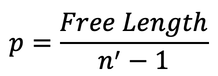
The pitch of the coil is defined as the axial distance between adjacent coils in an uncompressed state. Mathematically, the Pitch of the coil is

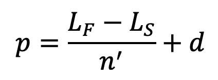
The pitch of the coil may also be obtained by using the following relation, i.e.
The pitch of the coil,

where
LF = Free length of the spring
LS = Solid length of the spring
n’ = Total number of coils
d = Diameter of the wire
In choosing the pitch of the coils, the following points should be noted:
- Thepitchofthecoilsshouldbesuchthatifthespringisaccidentlyorcarelesslycompressed, the stress does not increase the yield point stress in torsion.
- The spring should not close up before the maximum service load is reached
👉 Important Note:
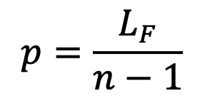
In designing a tension spring, the minimum gap between two coils when the spring is in the free state is taken as 1 mm. Thus the free length of the spring,
LF = n × d + (n–1)
and pitch of the coil,

End Connections for Compression Helical Springs
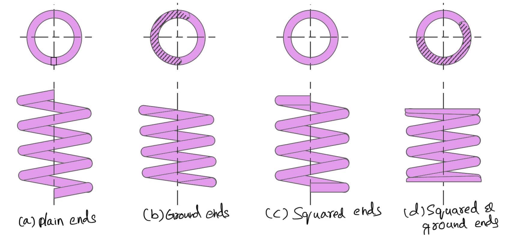
The end connections for compression helical springs are suitably formed to apply the load. Various forms of end connections are shown in the following figure.

In all springs, the end coils produce an eccentric application of the load, increasing the stress on one side of the spring. Under certain conditions, especially where the number of coils is small, this effect must be taken into account. The nearest approach to an axial load is secured by squared and ground ends, where the end turns are squared and then ground perpendicular to the helix axis.
It may be noted that part of the coil that is in contact with the seat does not contribute to spring action and hence is termed an inactive coil. The turns which impart spring action are known as active turns. As the load increases, the number of inactive coils also increases due to seating of the end coils and the amount of increase varies from 0.5 to 1 turn at the usual working loads. The following table shows the total number of turns, solid length, and free length for different types of end connections.
Table: Total number of turns, solid length, and free length for different types of end connections.
| Type of end | Total number of turns (n’) | Solid length | Free length |
| 1. Plain ends 2. Ground ends 3. Squared ends 4. Squared and ground ends | n n n+2 n+2 | (n + 1) d n×d (n + 3) d (n + 2) d | p×n+d p×n p × n + 3d p × n + 2d |
where
n = Number of active turns
p = Pitch of the coils
d = Diameter of the spring wire
This is all about the Compression Springs’ nomenclature and the End Connections for Compression Helical Springs. Let us know what you think about this article in the comment section below.

Leave a Reply