A truss is a structure made up of slender members or beams pin-connected at ends and is capable of taking loads at joints. Truss is a rigid structure. They are used as roof trusses to support sloping roofs and as bridge trusses to support the deck. In many machines, steel trusses are used. Transmission towers are also examples of trusses. In the case of wooden trusses, the ends are connected by making suitable joints or by nailing and bolting whereas in steel trusses ends are connected by bolting or welding. The trusses are also known as ‘pin-jointed frames’. Let us discuss more details on Trusses and see how we can calculate all forces in Truss.

A truss in which all the members lie in a single plane is called a plane truss. In such trusses loads act in the plane of the truss only. Roof trusses and bridge trusses can be considered plane trusses.
If all the members of a truss do not lie in a single plane, then it is called a space truss. Tripod and transmission towers are examples of space trusses.
The analysis of plane trusses is discussed below.
What is a Perfect Truss?
A pin-jointed truss that has got just a sufficient number of members to resist the loads without undergoing appreciable deformation in shape is called a perfect truss.
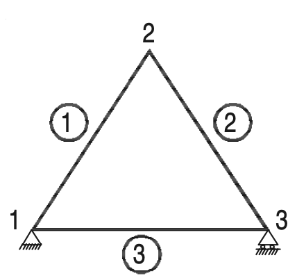
A triangular truss is the simplest perfect truss and it has three joints and three members as shown in the below figure.
Perfect trusses with four and five joints are shown in Figures (a) and (b) respectively.

It may be observed that to increase one joint in a perfect truss, two more members are required.
Hence the following expression may be written down as the relationship between a number of joints j, and the number of members m, in a perfect truss.
m = 2j – 3
However, the above equation gives only a necessary, but not sufficient condition of a perfect truss. For example, the two trusses are shown in Figures (a) and (b) have the same number of members and joints.
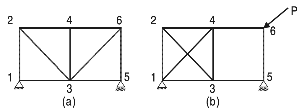
(b) Not a Perfect tress due to changing shape on applying load
The truss is shown in Figure (a) is perfect whereas the one shown in Figure (b) is not capable of retaining its shape if loaded at the joint marked 6. Therefore, the only necessary and sufficient condition of a perfect truss is that it should retain its shape when the load is applied at any joint in any direction.
What is a Deficient Truss?
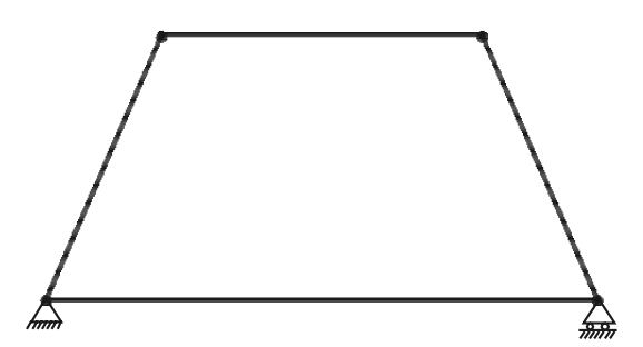
A truss is said to be deficient if the number of members in it is less than that required for a perfect truss. Such trusses cannot retain their shape when loaded. A deficient truss is shown in the below figure.
What is a Redundant Truss?
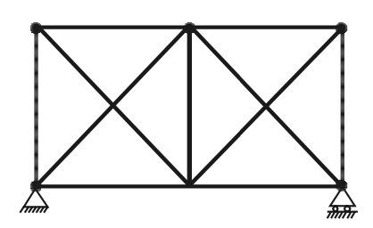
A truss is said to be redundant if the number of members in it is more than that required in a perfect truss. Such trusses cannot be analyzed by making use of the equations of equilibrium alone.
Thus, a redundant truss is statically indeterminate. Each extra member adds one degree of indeterminacy. For the analysis of such members, the consistency of deformations is to be considered. The truss shown below is a typical redundant truss. In this truss one diagonal member in each panel is extra. Hence it is a two-degree redundant truss.
Let us only consider the perfect Truss for the analysis and let us see how we can calculate all the forces in Truss.
Assumptions for Analysis of Truss
In the theory that is going to be developed in this chapter, the following assumptions are made:
(1) The ends of the members are pin-connected (hinged)
(2) The loads act only at the joints
(3) Self-weights of the members are negligible
(4) Cross-section of the members is uniform
If at all the cross-section varies, the center of gravity of the section is assumed to be located along the same longitudinal line.
In reality, the members are connected by bolting, riveting, or by welding. No special care is taken to ensure perfect pin-connections. However, experiments have shown that assuming pin-connected ends is quite satisfactory since the members used are slender.
Nature Of Forces In Truss Members
The members of a truss are subjected to either tensile or compressive forces. A typical truss ABCDE loaded at joint E is shown in the below figure (a).
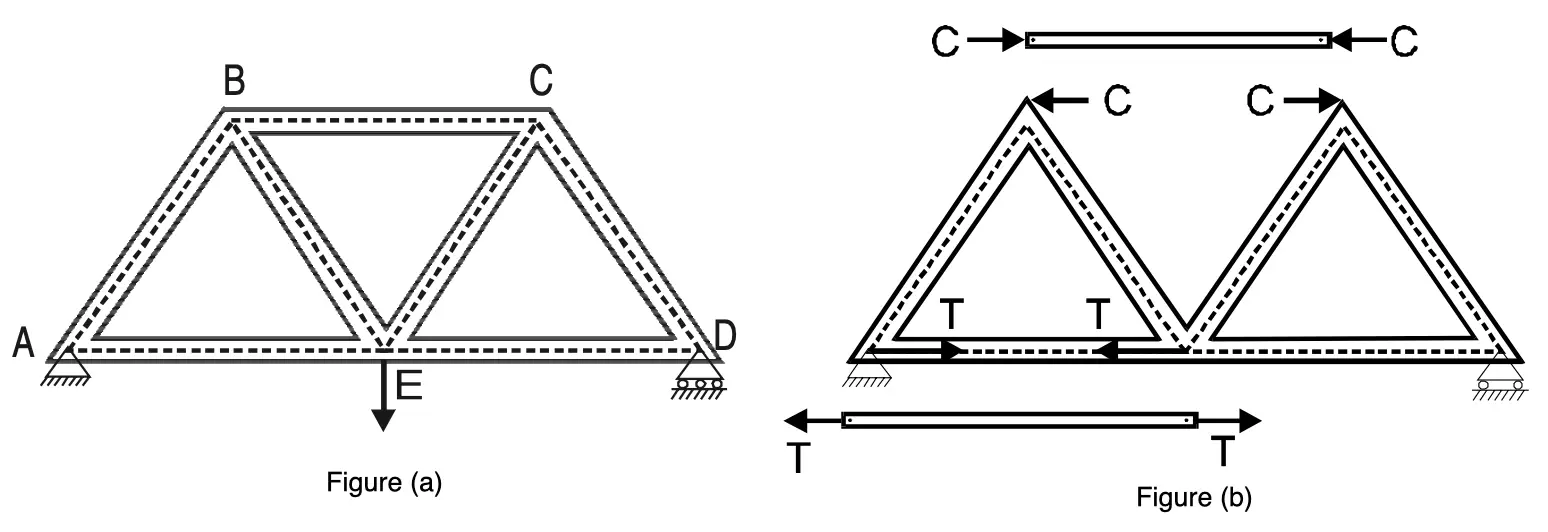
The member BC is subjected to compressive force C as shown in the above figure (b). The effect of this force on joint B (or C) is equal and opposite to the force C as shown in figure (b).
The member AE is subjected to tensile force T. Its effect on joints A and E are as shown in Figure (b) above. In the analysis of the frame, we mark the forces on the joints, instead of the forces in the members as shown in Figure below.
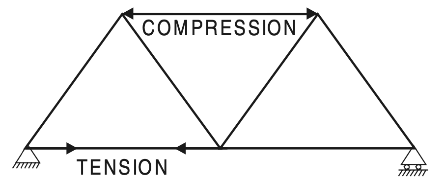
It may be noted that compressive force in a member is represented in a figure by two arrows going away from each other and a tensile force by two arrows coming towards each other. This is quite logical considering the fact that the markings on the members represent the internal reactive forces developed which are opposite in direction to the applied forces.
Methods Of Analysis
The following three methods are available for the analysis of pin-connected frames called Trusses.
(a) Method of joints
(b) Method of section
(c) Graphical method.
In the previous article, we have already discussed how to calculate Forces in Truss with help of Methods of Joints.
let us discuss how we can calculate the forces in Truss with help of the method of Section.
Calculating Forces in Truss by Method Of Section
- In the method of the section, after determining the reactions, a section line is drawn passing through not more than three members in which forces are not known such that the frame is cut into two separate parts.
- Each part should be in equilibrium under the action of loads, reactions, and forces in the members that are cut by the section line.
- Equilibrium of any one of these two parts is considered and the unknown forces in the members cut by the section line are determined.
- The system of forces acting on either part of the truss constitutes a non-concurrent force system.
- Since there are only three independent equations of equilibrium, there should be only three unknown forces.
- Hence, in this method, it is an essential condition that the section line should pass through not more than three members in which forces are not known and it should separate the frame into two parts.
Thus, the method of the section is the application of nonconcurrent force system analysis whereas the method of joints, described in the previous article was the application of analysis of concurrent force
system.
Under the following two conditions the method of the section is preferred over the method of joints:
(1) In a large truss in which forces in only a few members are required
(2) In the situation where the method of joints fails to start/proceed with the analysis
Let us solve 3 example problems on the method of the section. Examples 1 and 2 are the cases in which the method of the section is advantageous since forces in only a few members are required. Example 3 is the case in which the method of joints fails to start/proceed to get the solution.
In practice, the frames may be analyzed partly by the method of section and partly by the method of joints as illustrated in example 3, so please refer to the methods of Joint if you haven’t already.
Example Problems to calculate all Forces in Truss with help of Method Of Section
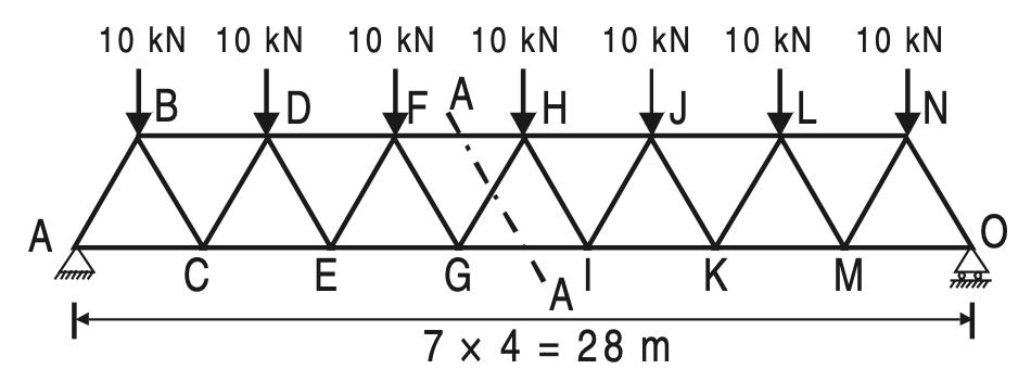
Example 1. Determine the forces in the members FH, HG, and GI in the truss shown in the below figure. Each load is 10 kN and all triangles are equilateral with sides 4 m.
Solution:
Due to symmetry,
RA = R0 = 1/2 × 10 × 7 = 35 kN
Take section (A)–(A), which cuts the members FH, GH, and GI and separates the truss into two parts.
Consider the equilibrium of the left-hand side part as shown in the below figure (Prefer part in which
a number of forces are less).
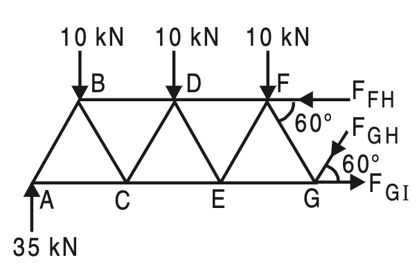
ΣMG = 0, gives
FFH × 4 sin 60° – 35 × 12 + 10 × 10 + 10 × 6 + 10 × 2 = 0
FFH = 69.2820 kN (Comp.)
∑V = 0, gives
FGH sin 60° + 10 + 10 + 10 – 35 = 0
FGH = 5.7735 kN (Compressive)
∑ H = 0, gives
FGI – FFH – FGH cos 60° = 0
FGI = 69.2820 + 5.7735 cos 60°
FGI = 72.1688 kN (Tension)
Example 2: Find the magnitude and nature of the forces in the members U3U4, L3L4, and U4L3 of the loaded truss shown in Figure.
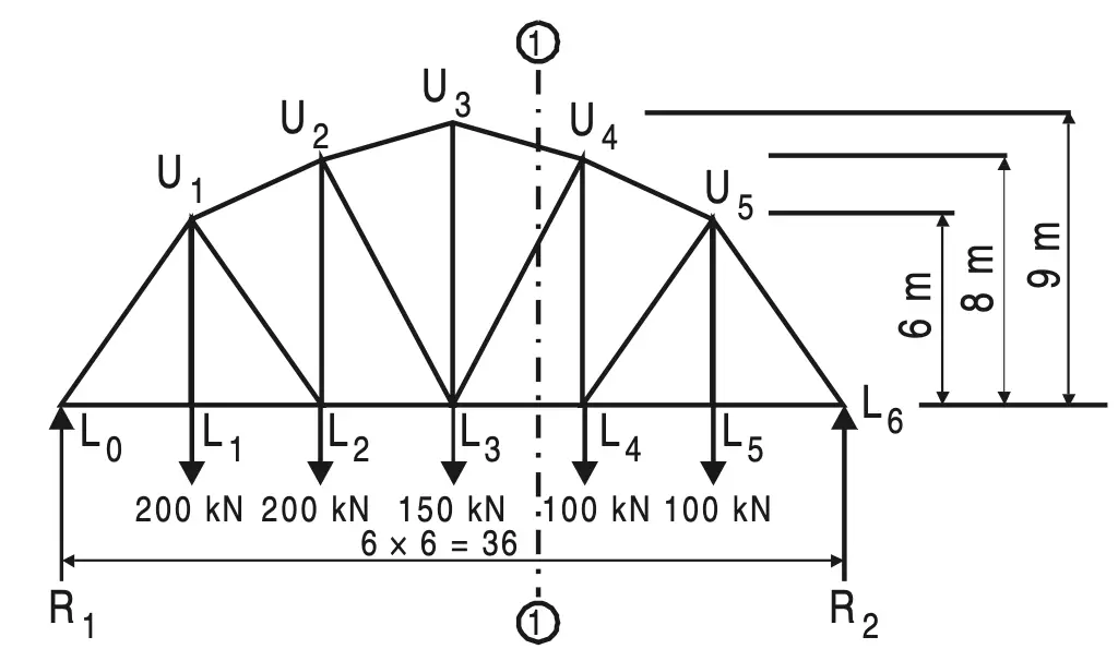
Solution:
To determine reactions, consider equilibrium equations.
Now, ∑ M LO = 0, gives
R2 × 36 – 200 × 6 – 200 × 12 – 150 × 18 – 100 × 24 – 100 × 30 = 0
R2 = 325 kN
∑V = 0, gives
R1 = 200 + 200 + 150 + 100 + 100 – 325
R1 = 425 kN
Take the section (1)–(1) and consider the right-hand side part.
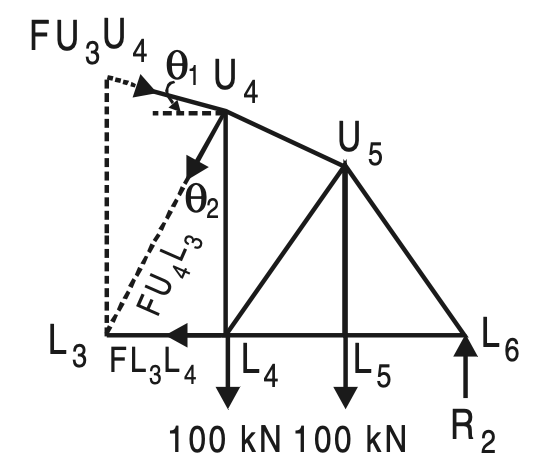
U3U4 = √(12 + 62) = 6.0828
sin θl = 1/6.0828 = 0.1644
cos θl = 6 /6.0828 = 0.9864
L3U4 = 62 + 82 =10
sin θ2 = 0.6 cos θ2 = 0.8
Σ MU4 = 0, gives
FL3L4 × 8 – 325 × 12 + 100 × 6 = 0
FL3L4 = 412.5 kN (Tension)
Σ ML3 = 0, gives
FU4U3 × cos θ1 × 9 + 100 × 6 + 100 × 12 – 325 × 18 = 0
FU4U3 = 456.2072 kN (Comp.)
∑ H = 0
FU4U3 sin θ2 – FU4U3 cos θ1 + FL4L3 = 0
FU4U3 = (456.2072 × 0.9864- 412.5)/ 0.6
FU4U3 = 62.5 kN (Tension)
Example 3: Find the forces in the members (1), (2), and (3) of the French truss shown in the below figure.
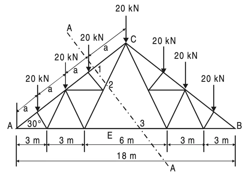
Solution:
Due to symmetry
RA = RB = (1/2) × 20 × 7 = 70 kN
AC = 4 × a = 9/cos 30°
∴ a = 2.5981 m
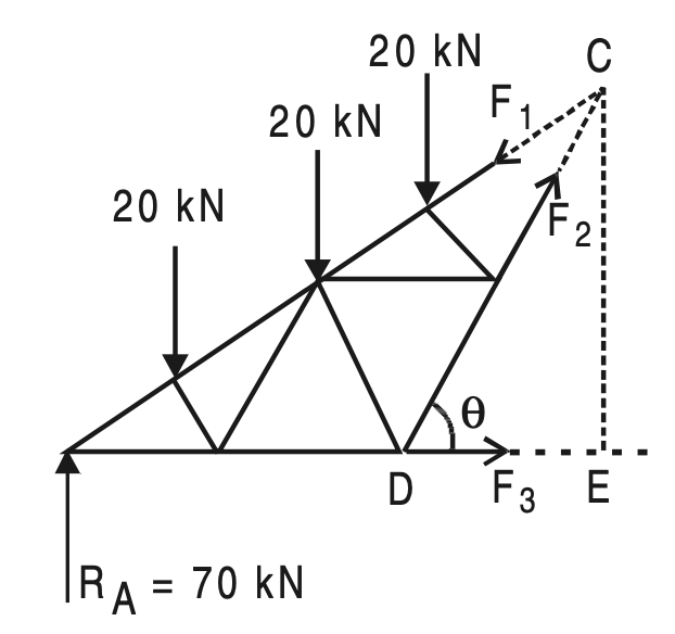
Take Section (A)–(A) and consider the equilibrium of the left-hand side part of the French Truss
shown in the above figure.
Drop perpendicular CE on AB.
CE = 9 tan 30°
DE = 3 m
∴ tan θ = (9 tan30)/3 =3 × 1/√3 =√3
∴ θ = 60°
∑ M A = 0, gives
F2 sin 60° × 6 – 20 × 2.5981 cos 30° – 20 × 2 × 2.5981 cos 30° – 20 × 3 × 2.5981 cos 30° = 0
F2 = 20 × 2.5981 (1+2+3)/6
We know sin 60° = cos 30°, and substitute we get
F2 = 51.9615 kN (Tension)
∑V = 0, gives
F1 sin 30° – 70 + 20 + 20 + 20 – 51.9615 sin 60° = 0
F1 = 110 kN (Comp.)
∑ H = 0, gives
F3 + F2 cos 60° – F1 cos 30° = 0
F3 = 69.2820 (Tension)
Note: In this problem, the method of joints cannot give a complete solution.
Conclusion
We have discussed what is a perfect truss, a Redundance truss, and a deficient Truss. We have listed the assumptions that we make to analyze the Truss, also list the types of forces in truss members. We calculated all the forces in the truss given in 3 example problems successfully with help of the method of section. Let us know what do you think about this article in the comment section below.

Leave a Reply